• Please review our updated Terms and Rules here

A pair of Pets - Preparing to test after perhaps 40 years unused

Port89

Experienced Member
Joined
Jun 10, 2023
Messages
131
Location
Sydney, Australia
Hi,

After learning about and repairing a number of 80's machines in the last 9 months (BBCs, C64s, Amiga, Amstrad, Archimedes, STs and Sinclairs), I'd deliberately left two machines in storage that were particularly special to me.

I knew and was intrigued by them as young kid in their business setting, and the original owner left them to me. I've only had them for about 20 years but I suspect that these haven't been in active use since 1985. He was a prolific buyer of tech so it wouldn't have been long until something else came along and these went onto the shelves where I saw them sit for decades.

Before I put a mains plug on them and see what happens....what should I know?

I'll add some inside pictures shortly.
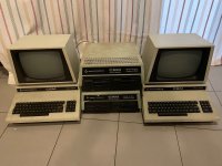
IMG_6867 - Copy.jpg
 
Very cool.. especially the 8250 drive. What I did on mine before powering it up:

- Check for cracked RIFAs and other suspicious filters that can explode (on mine it was under the metal cage holding the transformer)
- Reform the big smoothing capacitors (one per computer and two per disk drive)
- Check for shorts
- Clean dust and debris
- On first power up, measure the voltages at the DRAM chips
 
Thank you, good tips. I see something under one of my transformers and just looked up how that's maybe a tube with a few safety caps inside.

I'll start with reforming the big capacitor from what I presume is the older machine (serial 16110, the other is 23043). I've not done this before but after watching a Youtube I feel fully qualified, and have a good bench supply.

I hadn't even noticed the drives were different :) I just looked them up. Interesting that they seem to be higher spec than the later 1541's I'm used to.

I wonder if the actual monitors still work. These things were shipped a pretty long distance to me in fairly basic boxes just crammed with polystyrene. So far I can't see signs of any physical damage.
 
You might get different opinions on this.

I am not a "capacitor reformer believer" even though I might be a Monkees Daydream Believer.

The reason is that a main filter capacitor should always be up to scratch at power up. If not, regardless of its age and "potential" for rehabilitation, there is something wrong with it.

With the very vintage caps, you can get some that are "borderline" at power up, and after re-forming they do improve, for sure, but they will not go back to the new condition and have a narrower operating margin.

In the power supply, that means sustaining the voltage (charge in the capacitor) between the charging peaks, so that the voltage does not trough down too low and allow ripple to pass to the voltage regulator's outputs.

If I see an electrolytic capacitor not perform its task at power up, I deem it to be defective and don't try to save money by re-forming it. Attempting to rehabilitate it with reforming is somewhat like firing anti-inflammatory steroids into a racehorse's joints, when it has an injury that should really prohibit it from racing. Though, others swear by reforming.

A new capacitor is indicated if you want reliable long term results. One thing to get to grips with : "Electrolytic capacitors are a disposable item" much like the ink cartridges that come with your printer.

The main large filter capacitors for the PET are readily available.

Mostly, you will find the smaller electrolytic caps on the pcb are perfectly ok.
 

Attachments

  • MAINCAP.jpg
    MAINCAP.jpg
    299.5 KB · Views: 13
I am not a "capacitor reformer believer" even though I might be a Monkees Daydream Believer.

The reason is that a main filter capacitor should always be up to scratch at power up. If not, regardless of its age and "potential" for rehabilitation, there is something wrong with it.
Thank you - I see where you are coming from. I'm not a Daydream Believer but I'm trying my best to like the Now and Then :)

I've already had the 'big' capacitor hooked up and having started at 1V / 10mA and gradually increased the voltage as the current draw dropped back to zero, I pretty quickly got to 16V as witheach extra V it dropped within a second or so. It's been sitting at 16V for a few mins now as type this reply.

Does that suggest that this particular cap is perfectly healthy?

(for ongoing reference, I don't have an ESR tester but I do have a multimeter with capacitance on it. And a digital scope.)
 
Thank you, good tips. I see something under one of my transformers and just looked up how that's maybe a tube with a few safety caps inside.
Can you post the tube? Does it have wires sticking out? If so it might be one of those filters that like to explode and you're better off cutting it out. Long term I replace it with new filters even though many say it's unnecessary.

I hadn't even noticed the drives were different :) I just looked them up. Interesting that they seem to be higher spec than the later 1541's I'm used to.
The 8x50 line of drives were pretty high end and a 1541 is quite a step back from those

I wonder if the actual monitors still work. These things were shipped a pretty long distance to me in fairly basic boxes just crammed with polystyrene. So far I can't see signs of any physical damage.
Check the insides for loose connections and cracked PCBs if you are worried about shipping damage

You might get different opinions on this.

I am not a "capacitor reformer believer" even though I might be a Monkees Daydream Believer.

[...]
I'm not disputing any of this and you are probably right, but personally I don't want to power up anything with large capacitors inside before checking how they perform on a basic level.

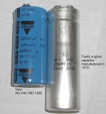
In my PET, the green capacitor was out of spec and I replaced with a KEMET part (similar to your picture), no hesitation. The capacitors in the disk drive performed as they should after reforming them and I didn't want to throw away a good part for nothing.

Does that suggest that this particular cap is perfectly healthy?

(for ongoing reference, I don't have an ESR tester but I do have a multimeter with capacitance on it. And a digital scope.)
I would say if it charges to the specified voltage and doesn't produce any significant leakage currents you are good to go for a first power up. You can still measure the ripple currents with your scope and replace capacitors as needed later.
 
Thank you - I see where you are coming from. I'm not a Daydream Believer but I'm trying my best to like the Now and Then :)

I've already had the 'big' capacitor hooked up and having started at 1V / 10mA and gradually increased the voltage as the current draw dropped back to zero, I pretty quickly got to 16V as witheach extra V it dropped within a second or so. It's been sitting at 16V for a few mins now as type this reply.

Does that suggest that this particular cap is perfectly healthy?

(for ongoing reference, I don't have an ESR tester but I do have a multimeter with capacitance on it. And a digital scope.)

One issue with these very large value uF capacitors, an ESR meter is not much use because even when they have lost capacity, the ESR still measures very low. Also the uF value is often outside the range of many capacitance meters.

Measuring the average DC voltage across the capacitor doesn't always tell the whole story either.

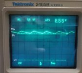
However, the simple test is to look at the voltage waveform across the capacitor's terminals with the scope.

They charge on peaks via the diodes at twice the line frequency. At times in between they are discharging.

Provided the voltage they discharge to, before the next re-charge, is higher than the required minimum input voltage to the 5V regulator, which is typically 7.5V, then no ripple will break through to the regulator's output.

Though, ideally this voltage trough should be higher than this, at least 8.5 to 9V to allow for fluctuations in line voltage that drop 10 to 15% below the nominal line voltage.

The test is done with the scope on DC coupling. The beam position with zero volts being about 1cm up from the bottom of the graticule and the scope sensitivity on 2V/cm.

Photo of the voltage across the new capacitor in my PET attached.

When the capacitor has lost capacity, it discharges at a faster rate, and the voltage dips can reach the regulator outputs. This was the case with my original PET capacitor.
 

Attachments

  • PETRIPPLE.jpg
    PETRIPPLE.jpg
    180.4 KB · Views: 16
Can you post the tube? Does it have wires sticking out? If so it might be one of those filters that like to explode and you're better off cutting it out. Long term I replace it with new filters even though many say it's unnecessary.

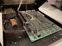
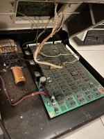
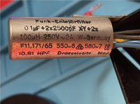
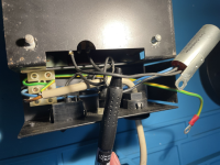
Here are two views of the tube (choke as I now realise it's called). The Youtube I watched also just bypassed it. Is that safe enough for the time (eg worst case is instability or not working) being or am I risking damage to the machine to some degree? People seem to be selling these, but maybe they are old / used stock which may defeat purpose here.

You can perhaps see in the second photo that my 'tube' has no evidence of popping in the way I saw in the video. That said, I've experienced first hand the safety caps (yes, Rifa) exploding in my face / plume of acrid smoke after being powered on for the first time in decades. Presumably this may do the same. I don't see any other similar caps elsewhere in the machine, although I haven't tried to inspect the monitor section yet.

CBM8032-XYTube-small.png CBM8032-powerinput-small.png

Check the insides for loose connections and cracked PCBs if you are worried about shipping damage

Having pulled the transformer cage apart and removed the motherboard for light dusting/IPA brushing and close inspection, it looks to be in very good shape.

There's some mild surface corrosion (brown, not green) on IC legs etc but nothing that looks like it will matter much.

There are only a couple of indicators or rework which I suspect were repairs during manufacture or it's original service life. Eg UC6 is socketed with browning on underside were maybe it wasn't cleaned up properly. It's also a Mitsibushi part (M5L2114LP-3) not like the similar 2114 chips around it.


One issue with these very large value uF capacitors, an ESR meter is not much use because even when they have lost capacity, the ESR still measures very low. Also the uF value is often outside the range of many capacitance meters.
Yeah, I realised that when I couldn't get a reading and pulled out some random small caps to check my multimeter (the eevblog 786) wasn't faulty. Then I realised that 22000 MFD / uF is way beyond what it's meant for.

I'd like to learn how to do that ripples check shown - everything I look up is also using a waveform generator which I don't have (unless I cound a little RPi / resister ladder one I assembled from some blog post). Were you measuring with it back in your running machine? If so I'll wait until I'm at that point.


In closing for this reply.....if I see no physical damage, I've cleaned up the dust and debris, I'll potentially bypass the XY filter tube and the big smothing capacitor seems to be working well enough....is that time to try power on or do I need to over the monitor first?
 
Last edited:
Here are two views of the tube (choke as I now realise it's called). The Youtube I watched also just bypassed it. Is that safe enough for the time (eg worst case is instability or not working) being or am I risking damage to the machine to some degree? People seem to be selling these, but maybe they are old / used stock which may defeat purpose here.

You can perhaps see in the second photo that my 'tube' has no evidence of popping in the way I saw in the video. That said, I've experienced first hand the safety caps (yes, Rifa) exploding in my face / plume of acrid smoke after being powered on for the first time in decades. Presumably this may do the same. I don't see any other similar caps elsewhere in the machine, although I haven't tried to inspect the monitor section yet.

View attachment 1267364 View attachment 1267366
Yeah, those must go, they can pop similar to old RIFA caps.

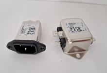
If you must replace it I don't know, I guess it depends on the circumstances. I do it because I like having a bit of filtering and noise suppression on those old machines. When I replace them I pick one that fits physically and has the same amperage rating as the old one (see attachments for examples).
I'd like to learn how to do that ripples check shown - everything I look up is also using a waveform generator which I don't have (unless I cound a little RPi / resister ladder one I assembled from some blog post). Were you measuring with it back in your running machine? If so I'll wait until I'm at that point.
To measure ripple with higher resolution, you can set your scope to AC coupling, 1x and use the shortest ground lead you can find (ideally you use ground springs on probe). The ground springs are a bit fiddly though, they're meant for test points where Vcc and gnd are close to eachother. If you use a longer ground lead be aware that it will falsify the results. The ripple should be in the mV range for this type of device.

Hugo measurement is the voltage on the big capacitor, no need for any special equipment for that besides your scope set for DC measurements (you should see the same waveform on AC coupling, but without the offset)
In closing for this reply.....if I see no physical damage, I've cleaned up the dust and debris, I'll potentially bypass the XY filter tube and the big smothing capacitor seems to be working well enough....is that time to try power on or do I need to over the monitor first?
If you suspect shipping damage have a look inside the monitor case, otherwise go for it (and keep an eye on the three voltage rails after regulation)
 

Attachments

  • 20231104_091216.jpg
    20231104_091216.jpg
    660.6 KB · Views: 7
Here are two views of the tube (choke as I now realise it's called). The Youtube I watched also just bypassed it. Is that safe enough for the time (eg worst case is instability or not working) being or am I risking damage to the machine to some degree? People seem to be selling these, but maybe they are old / used stock which may defeat purpose here.

You can perhaps see in the second photo that my 'tube' has no evidence of popping in the way I saw in the video. That said, I've experienced first hand the safety caps (yes, Rifa) exploding in my face / plume of acrid smoke after being powered on for the first time in decades. Presumably this may do the same. I don't see any other similar caps elsewhere in the machine, although I haven't tried to inspect the monitor section yet.

View attachment 1267364 View attachment 1267366


Having pulled the transformer cage apart and removed the motherboard for light dusting/IPA brushing and close inspection, it looks to be in very good shape.

There's some mild surface corrosion (brown, not green) on IC legs etc but nothing that looks like it will matter much.

There are only a couple of indicators or rework which I suspect were repairs during manufacture or it's original service life. Eg UC6 is socketed with browning on underside were maybe it wasn't cleaned up properly. It's also a Mitsibushi part (M5L2114LP-3) not like the similar 2114 chips around it.


Yeah, I realised that when I couldn't get a reading and pulled out some random small caps to check my multimeter (the eevblog 786) wasn't faulty. Then I realised that 22000 MFD / uF is way beyond what it's meant for.

I'd like to learn how to do that ripples check shown - everything I look up is also using a waveform generator which I don't have (unless I cound a little RPi / resister ladder one I assembled from some blog post). Were you measuring with it back in your running machine? If so I'll wait until I'm at that point.


In closing for this reply.....if I see no physical damage, I've cleaned up the dust and debris, I'll potentially bypass the XY filter tube and the big smothing capacitor seems to be working well enough....is that time to try power on or do I need to over the monitor first?
Yes, it is running in the machine with the pcb drawing normal currents. Otherwise the 22,000 uF capacitor would not be discharging between peaks due to the current drain from the pcb.

Don't get too excited about the filter units on the incoming line voltage on the transformer primary side. Most of the time it is better to throw them in the trash.

They serve no useful purpose on an analog supply.

On SMPS's they help filter RF hash off the line, from the device you have injecting it into the line power source.

With an analog supply, like a transformer, the only useful application the input filter has is to shield the PET from incoming RF hash on the line power. There is a lot these days with many SMPS's on the line

But it is not required, because the power transformer in the PET, with its inductive properties, does a lovely job of that for you.

While one could argue the filter caps and inductors placed in the line power feed on an analog supply have some merit, it is offset by the unreliability of the capacitors, particularly X2 types. Most were made with metallised paper and the plastic casings split over time. They absorb moisture and swell up. Then later they smoke an burn up. The Rifa X2's are notorious for this. They don't "explode" that is melodramatic hyperbole, but they do burn up and will smoke out a room and can char the pcb surface for pcb mounted X2's, very unpleasant.

It is reasonable to replace things like X2 capacitors on SMPS supplies and it keeps the RF hash off the 115 or 230V supply line to be considerate to others (like washing your hands after you go to the toilet, it protects others, not you).

If you are super concerned about RFI on the line power (I wouldn't be) you can always fit a panel mount IEC connector that has inductors and filter caps in it. But like I say, when you are feeding the transformer primary, like you are in the PET, there is very little to be gained.

Another bit of advice, don't watch youtube videos on technical matters. Stick to books on the topic, where the material has been screened by experts in the area, before the publisher was willing to spend the money to put it into print and be as sure as possible that the content was accurate. I have seen so much nonsense on youtube videos related to electronic repairs, that it beggars belief.

It was suggested that you put your scope on AC coupling. While that might help you inspect the magnitude of the ripple voltage, that is not the important thing. What you are interested in is the lowest point that the ripple voltage falls to, because it must be (in the case of a 5 V analog voltage regulator) 7.5V or higher. If you switch the scope to AC coupling, you cannot determine this.
 
Last edited:
With the input filter / choke / tube bypassed & removed, I reassembled everything and powered on.

- I got what sounded like 4 of beeps, and with a bit of Google, it was the same as I hear on other peoples Pets. Not intentionally, but I managed to consciously hear that on a real one before hearing it online so I wasn't sure if it was a good thing or not.
- No screen output.
- I powered off after about 10 seconds so I could move the machine around as I couldn't get in with my multimeter probes properly
- Second power on also made the beeps but still no display so I started by measuring output on the transformer itself.
- As I measured 20 VAC on the output to the monitor (is that OK? docs say 21 for the 12" screen) I heard a 'fizzleing sound, and saw some smoke rising from a now burned out C59 - powered off quickly

I need to call it night for now but I guess I won't be applying power to the board again until I know what caused that and replace C59.
 
Where is C59 on your schematic ? What sort of cap is it ? If it is a Tant cap, it will be the fault of the capacitor, nothing else.
 
You should remove the mains filter - they are nasty when they fail and they DO... you won't forget the smell or smoke in a hurry....
 
I see you have two (2) PET's - both identified on the case as 8032. However, each PET has a different main board.

In both cases, however, C59 is a very simple ceramic axial 0.1uf decoupling capacitor rated at 50V on the +5V rail. This would take a lot of effort to make it smoke.

Can you confirm which board C59 is on and post a photograph of the casualty please.

It is ALWAYS best to disconnect the power connector from the PET board BEFORE doing anything else and then measuring the AC voltages from the transformer. I would also disconnect the AC supply within the monitor also.

I am a great believe in checking the capacitors before I power up - especially the large smoothing electrolytics. If they have a high leakage then I would either attempt a reform or replace (depending upon how expensive the capacitors were and how historical the machine is). I do this to protect myself in case they go bang!

Dave
 
Occasionally a 0.1uF capacitor can short out an burn up when the power supply can source a large current. Usually its the monolithic ceramic types that can do it rather than a vintage disc ceramic and it is much less common than a Tant cap doing it, these short out with monotonous regularity.

The only capacitor I would perform a re-forming process on, in an attempt to save it, are the gigantic ones in the region of 50,000uF in things like S-100 computers, the main reason being these parts are becoming more rare now and very expensive in a physical size that matches the originals , largely because SMPS took over and require much lower value caps, because they operate at a much higher frequency than the analog line powered supply. For this reason I bought a spare main capacitor for my SOL-20 just in case. So it is worth a go with these but a reformed part from the 70's won't be as good as a new one.

The type of main filter cap used in the PET, being close to 22,000uF is still a "fairly" current part. Interestingly (since I got mine from RS) they are now out of stock at both RS and Mouser, but Digikey still has 158 of them. Not cheap, but $35 USD, or $58 AUD, is not that bad, you get what you pay for. I would advise all PET owners who still have the original 70's vintage 23,000uF electrolytic in their PET to buy one of these as a spare, before they go unavailable, which is on the cards, because I cannot think of any new design equipment that will be likely to require such a part, except perhaps for Audio power Amps where the enthusiasts insist on analog supplies:


Notice the astonishingly low ESR of 20m Ohms and the 10,000 hrs running time at @ 85C, it will be running much lower temp in the PET and last easily 4 or 5 times that. This is typical of large body capacitors as because with ripple currents they don't heat up much with the low ESR and and run very cool, unless somebody is silly enough to clamp them to a heat-sink. I chose this 40V part so its physical size better resembled the original PET capacitor. Modern electrolytic capacitors have a much smaller volume than those from the 1970's era for the same uF and voltage rating. Part of the fun of the vintage computer is the large sized capacitors in the analog supplies, it adds to the charm.

For S-100 computers, a 47,000uF capacitor like this, 2.5" diameter and 4" tall, which is a physical size match and close uF value match for the SOL-20 computer and other S-100 computers, is not a cheap part at $73 USD or $120 AU. I would say these will be gone for sure in the next 5 or 10 years. Probably it will result in a lot of the vintage computers in the future being made non-original with SMPS supplies added instead. If you have an S-100 computer it might pay to put some of these beauties in your Xmas stocking:

 
Last edited:
Where is C59 on your schematic ? What sort of cap is it ?

It's a 0.1uF 50V ceramic.. I'm still at the 'I've no idea what is where' on this board so all I can say at this point is "in the top right corner" at this point (I know that's not what you were asking). I don't know what role it's generally playing yet.

Can you confirm which board C59 is on and post a photograph of the casualty please.
Good point, both of my 8032's have different boards.
The one I chose to start working on so in context now is the 8032090 'Universal Dynamic Pet'. The one I haven't touched yet is marked '80 column' instead.

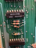
The now broken C59 is below. It looked visibibly chared amongst the components in the area where I saw the smoke rising, although I can't swear that it was definitely this component. I jumped to this conclusion based on it looking burned then cracking with light presure from my fingersNo others in the areas seem to look burned. While this clearnly need replaced, I'm not rulling out that the smoke could have been something else.

IMG_6906.jpeg
Occasionally a 0.1uF capacitor can short out an burn up when the power supply can source a large current. Usually its the monolithic ceramic types that can do it rather than a vintage disc ceramic and it is much less common than a Tant cap doing it, these short out with monotonous regularity.
Hopefully that's what's happened! I've gone over the area with a magnifing glass (literally) and nothing else seems to have any evidence of overheating although I wonder what the two transistors Q1/Q2 do and whether they get hot and could have been burning off some debris hidden underneath.

There is a tantalum cap in the same area (C51) but it looks to be physically intact, I had a very close look.

you won't forget the smell or smoke in a hurry
Yes - I've experienced it with a BBC Model B 😀 - room stunk for days.

Back to the transformer, which I've disconnected from the monitor and board again: What should I be measuring at specific points on it's 8 outputs?
 
Last edited:
You do know the schematics and board layout are all over at zimmers...

Dave
I do, started reading yesterday. I've still not got my head around them at all though.

edit: I've found C59, on the voltage regulation diagram. Looks like it sits directly on the +5V.
 
Last edited:
Back
Top