• Please review our updated Terms and Rules here

A PET storage option

The Commodore Universal Wedge or "DOS Support" utility is sort of working with the PETdisk as device 8. While the directory command >$ gives the same error as the BASIC 4 DIRECTORY command and BATPRO, the LOAD command /filename works fine. However, if you tried a >$ first, then the load will get a ?file not found error. But the second attempt will work. This is pretty good considering the designer did not take any of the PET utilities into account with his initial design. He advertized LOAD and SAVE commands and they work great.

I did manage to corrupt the PETdisk a little by saving some long filenames either on the PET side or the PC side (I don't remember) and got some funny looking filenames when reading the directory on the PET. The other files work fine, but I decided to reformat the SD anyway.

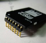
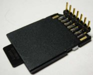
I wish the gadget used the standard SD chip instead of the microSD because while with a little trouble I can pull the microSD out of the adapter while it is attached to the PET connector, it is so teensy that I cannot insert it into the adapter without first pulling the gadget off the PET.
 
I wish the gadget used the standard SD chip instead of the microSD because while with a little trouble I can pull the microSD out of the adapter while it is attached to the PET connector, it is so teensy that I cannot insert it into the adapter without first pulling the gadget off the PET.

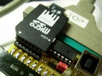
It's a little late, of course, but if a Rev 3 were in the works I wonder how possible it would be to roll over the connection pins so the MicroSD connector faced the other direction. I don't really have a problem with microSD but I can't even manage to pull the card out of the soldered-in adapter while it's on the pet because the little "thumb-notch" faces the back of the PET rather than the outside.

(I've pondered solving this problem by just bending the pins so the MicroSD adapter lays down flat over the top of the card instead of sticking up. Then I'd be able to get a fingernail in the notch.)

Gubbish: Any progress on getting a more formal documentation and source repository page up? It's not like I'd have oodles of time to poke at it any time soon but in *theory*...
 
While the directory command >$ gives the same error as the BASIC 4 DIRECTORY command and BATPRO,

After playing with DOS Support a little, I found that by doing a /$ one time, afterwards then, the >$ will always correctly list the PETdisk directory straight to the screen without loading it into RAM first. The /$ acts the same as LOAD"$",8 and needs a LIST to see the directory on the screen.

Oddly, after doing other work like loading other programs, trying a >$ to list the directory can get an error. But it can be cleared by doing a /$ once or twice.
 
Thanks for the user reviews,

I agree about the direction of the uSD adapter. While laying it out, I put pin 1 at the top of the board, just because - and didn't take the proximity to the back of the PET into consideration. In a future rev of the board, I would definitely like to not only turn the sd adapter around but also move it to the other side of the mcu chip, to place it further away from the back of the PET.
Bending the pins on the adapter, or just using a right-angle 7-pin header would also be a reasonable solution to get at the uSD card. I also tried cutting the plastic a bit on the uSD adapter to grip the uSD from the other side, that worked somewhat. Also a fix could be some sort of socket adapter that reverses the pins.
It's interesting to hear that the PETdisk works at all with some of the different types of commands.
Most likely what happened with the corrupt file names is saving a long file name from the PET side. This doesn't have an error check at the moment. Another on the list of things for a new firmware version.

I've been out of town for a while, so haven't had a chance to put the code up, but will do that as soon as I get a chance after I get back home tomorrow.
Thanks again and please keep the reports coming. Happy to fix any problems if I possibly can.
 
Last edited:
Thanks for the user reviews,

I agree about the direction of the uSD adapter. While laying it out, I put pin 1 at the top of the board, just because - and didn't take the proximity to the back of the PET into consideration. In a future rev of the board, I would definitely like to not only turn the sd adapter around but also move it to the other side of the mcu chip, to place it further away from the back of the PET.
Bending the pins on the adapter, or just using a right-angle 7-pin header would also be a reasonable solution to get at the uSD card.
Well, instead of turning it around I'd leave it the way it is, with a 90 degree bend on the SD adapter pins; if you're looking over the top of the PET you'll be able to see what you're doing.

PETdisk1.JPG PETdisk2.JPG PETdisk3.JPG

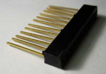
Or you could make an adapter by bending the pins on a single-row WW header like this:

PETdisk4.JPG

C'mon, Dave, get stronger glasses ;-) Using the adapter that comes with every uSD card as a free socket is brilliant!
 
Last edited:
I like the 90 degree header Mike - looks like yours is ready for duty. Were you able to get it working ok?
Another idea that just occurred to me is using a small piece of tape attached to the back of the uSD card as a handle for easy removal. It shouldn't interfere with inserting the card, and you could pull the uSD card out a bit more easily. Just another thought.
 
And another thought -
if there were a row of small clips that were in the place of the single-row socket, then a regular SD card could be used instead of a uSD if desired. It would need to be a clip that would make contact with the SD leads and also hold the card in place. I tried doing something like this with a vertical header with a plastic clip on the back, and it kind of worked. If there were a more suitable clip header, it could be possible to use regular SD media.
 
I like the 90 degree header Mike - looks like yours is ready for duty. Were you able to get it working ok?
Haven't had time to set it up yet, but soon.
Another idea that just occurred to me is using a small piece of tape attached to the back of the uSD card as a handle for easy removal. It shouldn't interfere with inserting the card, and you could pull the uSD card out a bit more easily. Just another thought.
I suppose, but when it lies flat like that it's no problem at all to just hook it with your thumbnail.

It's gonna be hard to find a 4" USB A to B cable; any reason why you couldn't dispense with the type B jack and just solder in a short cut-off USB cable?
 
And another thought -
if there were a row of small clips that were in the place of the single-row socket, then a regular SD card could be used instead of a uSD if desired. It would need to be a clip that would make contact with the SD leads and also hold the card in place. I tried doing something like this with a vertical header with a plastic clip on the back, and it kind of worked. If there were a more suitable clip header, it could be possible to use regular SD media.
Don't listen to Dave, microSD is fine! ;-)

But if you insist and don't mind a kludge like your cassette connector, I think a regular SD card would fit in a cut-off .100 card edge socket like the ISA bus connectors. Not enough room though; maybe a socket like you have now, but longer, with the partitions removed?
 
Last edited:
C'mon, Dave, get stronger glasses ;-) Using the adapter that comes with every uSD card as a free socket is brilliant!

For once I agree with you! :D

The alternate schemes you have come up with should fix the problem of thick-thumbed users.

What were you anyway in your former life? A real mechanical engineer?? ;)
 
For once I agree with you! :D
I'm writing the date in my calendar !!! I'm actually getting used to you pointing out the obvious flaws in most of my suggestions, sort of the Abbott to my Costello ;-)

The alternate schemes you have come up with should fix the problem of thick-thumbed users.

What were you anyway in your former life? A real mechanical engineer?? ;)
No, but kludge is my middle name.

BTW, Gubbish sounds a little interested in making a stripped-down equivalent to Nicolas' RAM/ROM board, now that Nicolas doesn't seem very interested in it any longer. Work on him a bit!
 
BTW, Gubbish sounds a little interested in making a stripped-down equivalent to Nicolas' RAM/ROM board, now that Nicolas doesn't seem very interested in it any longer. Work on him a bit!

That is good news. While I know little of designing PCB's, I have been stocking the programmable parts that go into the Nick board. I can supply the 128K EPROM equivalent (27C010) to the flash memory and the PAL16V8 (equivalent to the GAL16V8 ) for the address decoding.

Why are you talking 'stripped down'? I was thinking of ADDING your NOP Generator in either hardware or in firmware (if we wanted to dedicate 64K of NOPs in the EPROM).

Also I wanted a mode for diagnostics which would have 4K of code in the F000 area coming from the new board and the rest of the address space in the PET enabled to test ROMs, RAM and I/O. We could start with Eud's code and go from there. We would need to add a routine to initialize the 6545.

I noticed the register constants are a little different for each type of PET video, so we may need a test of the PET type in our code to use the correct constants.

I'm pretty sure there are enough product terms in the PAL16V8 to handle all the new equation requirements for this addressing. My old PROM programmer can handle both the 27C010 and the PAL so I would be responsible for fusing the parts.

Do you think we can all collaborate on this project?
 
I meant stripped-down as in not necessarily supporting disk drives and maybe not even VIC/64, but I suppose while you're at it... Some good ideas there for sure.

On the other hand, feature creep often means a project gets discussed a lot but never actually built... ;-)
 
Also I wanted a mode for diagnostics which would have 4K of code in the F000 area coming from the new board and the rest of the address space in the PET enabled to test ROMs, RAM and I/O. We could start with Eud's code and go from there. We would need to add a routine to initialize the 6545.

I noticed the register constants are a little different for each type of PET video, so we may need a test of the PET type in our code to use the correct constants.

This sounds like a neat idea! Just wanted to offer myself as another resource if needed.

I've written my own diagnostic ROM (inspired by Eud's solution) which currently works w/ 2001N and 40-COL CRTC PETs (assemble w/ different command line switches for the desired model).

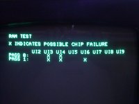
One neat feature is it will indicate which RAM chips need replacing (identifiers are different per machine supported). Example:

ram_test.jpg

Happy to send anyone the current source, or collaborate on new features.

Brandon
 
I've written my own diagnostic ROM (inspired by Eud's solution) which currently works w/ 2001N and 40-COL CRTC PETs (assemble w/ different command line switches for the desired model).

One neat feature is it will indicate which RAM chips need replacing (identifiers are different per machine supported).

Analog,
This looks good. You and Eud will be in charge of diagnostic software. I was thinking that if the target PET had problems with displaying a screen, we should also send error codes out to the User Port with test results as a backup.
-Dave
 
Also I wanted a mode for diagnostics which would have 4K of code in the F000 area coming from the new board and the rest of the address space in the PET enabled to test ROMs, RAM and I/O. We could start with Eud's code and go from there. We would need to add a routine to initialize the 6545.

(snip)

Do you think we can all collaborate on this project?

I'd be happy to see what I can do to improve the PETTESTER code enough to be more generally useful. Is there a good reference for how to program the 6545 in the PET? (A commentary of the code in the CRTC EDIT ROMs would be a start.) I've been wondering about how difficult it would be to program for other reasons anyway. (I'm somewhat curious if it would be possible to program the CRTC PETs so their video output happens at real "according to Hoyle" NTSC scan rates instead of the oddball PET monitor ones.) The one issue I could see is it might be necessary to have a jumper or some other way to config the board so it uses the correct initialization code for a given PET. (There are 50 and 60hz CRTC ROMs in addition to there being 40 and 80 column variants. Perhaps you could autodetect 40/80 column by seeing how much video RAM there is but 50/60hz is still a problem.

If the idea is to remake the board from whole cloth would there be any attraction to the idea of perhaps trying to use a 5v flash memory instead of an EPROM to allow the board to be programed in-situ? (Or, a really wacky idea: Forget having an EPROM at all. Make a board that has 128k or more of SRAM on it and has a small microcontroller and a couple latches that can load your desired firmware into a section of SRAM and write-protect it. The firmware could thus live on a small SPI-connected flash device and selection could be made via a serial line or something.)
 
This sounds like a neat idea! Just wanted to offer myself as another resource if needed.

I've written my own diagnostic ROM (inspired by Eud's solution) which currently works w/ 2001N and 40-COL CRTC PETs (assemble w/ different command line switches for the desired model).

One neat feature is it will indicate which RAM chips need replacing (identifiers are different per machine supported). Example:

View attachment 6535

Happy to send anyone the current source, or collaborate on new features.

I'd be really interested to see the source! I managed to bang out my little ROM code in a few hours of scratching my head but I'm a 6502 assembly newb, so I'd love to see something actually well done. Does your ROM manage to get any testing done before hitting the zero page or stack area?
 
Is there a good reference for how to program the 6545 in the PET? (A commentary of the code in the CRTC EDIT ROMs would be a start.)

The PET initializes the 6545 CRT controller by loading 17 registers with data. Here is the code (some of my comments may be wrong). If you can’t find a spec sheet on the 6545/6845, I’ll post the pdf.

Code:
; Initialize CRTC -- Patch for BASIC 4 or 80 columns?

 E07A    iE07A    LDA #$2A
 E07C        LDX #$E7
 E07E        LDY #$0E
 E080        BNE $E088


; Initialize CRTC --

 E082    iE082    LDA #$3C        ; this adress for 40 column or BASIC2???
 E084        LDX #$E7
 E086        LDY #$0C
 E088    iE088    STA $C7        ; Store address of CRTC constant table at C7 and C8 (low byte, hi byte)
 E08A        STX $C8
 E08C        LDA $E84C
 E08F        AND #$F0
 E091        STA $D1        ; Length of Current File Name; temp use of this location?
 E093        TYA
 E094        ORA $D1        ; Length of Current File Name???
 E096        STA $E84C        ; Selects lower case for business or upper case/graphics  
 E099        LDY #$11    ; Prepare to store 17 bytes from address E72A into the CRTC registers
 E09B    iE09B    LDA ($C7),Y    ; load next CRTC constant, indexed by Y register
 E09D        STY $E880    ; Store 6545/6845 CRT Controller Register Number (select the register)
 E0A0        STA $E881    ; Store 6545/6845 CRT Controller Register Data (transfer data into register)
 E0A3        DEY        ; decrement Y
 E0A4        BPL $E09B    ; If not finished, branch back to $E09B
 E0A6        RTS


; -    Video Chip Setup Table -- e07a        DATA BASIC 4?

 E72A        .byte 31 28 29 0F 27 00 19 20  ;1().'.. 
 E732        .byte 00 09 00 00 10 00 00 00  ;........
 E73A        .byte 00 00                    ;..


; -    Video Chip Setup Table -- e08a        DATA BASIC 2 or 40 column?

 E73C        .byte 31 28 29 0F 31 00 19 25  ;1().1..%
 E744        .byte 00 07 00 00 10 00 00 00  ;........
 E74C        .byte 00                       ;.


The one issue I could see is it might be necessary to have a jumper or some other way to config the board so it uses the correct initialization code for a given PET. (There are 50 and 60hz CRTC ROMs in addition to there being 40 and 80 column variants. Perhaps you could autodetect 40/80 column by seeing how much video RAM there is but 50/60hz is still a problem.

I had thought to read some locations in ROM to tell what kind of PET, but you have a point, what if the ROM is bad?

If the idea is to remake the board from whole cloth would there be any attraction to the idea of perhaps trying to use a 5v flash memory instead of an EPROM to allow the board to be programed in-situ? (Or, a really wacky idea: Forget having an EPROM at all. Make a board that has 128k or more of SRAM on it and has a small microcontroller and a couple latches that can load your desired firmware into a section of SRAM and write-protect it. The firmware could thus live on a small SPI-connected flash device and selection could be made via a serial line or something.)

The Nick board has a 128K Flash although I’m not sure that it can be reprogrammed in circuit. I mentioned the 27C010 EPROM only because I have some to donate. In circuit re-programming may be the best solution if we think there will be a lot of updates or want max flexibility in loading every version of PET BASIC for every version of CRT and keyboard. If we simply ask the user to tell us his configuration, then less flexibility may be needed.

The idea of a microcontroller and RAM is intriguing as long as the price stays low. PET people are cheap. :)
-Dave
 
I'd be really interested to see the source! I managed to bang out my little ROM code in a few hours of scratching my head but I'm a 6502 assembly newb, so I'd love to see something actually well done. Does your ROM manage to get any testing done before hitting the zero page or stack area?
Sent you a PM. The code tests the entire lower 16KB and is meant to verify the machine is in a reliable enough state before performing more in depth diagnostics (robust ROM checksums, etc) which require the use of RAM.
 
Where's the troubleshooting guide? ;-)

Formatted the uSD card, put a program on it, plugged everything in and "Device not present"...

Something dumb overlooked? Ideas where to start looking?
 
Back
Top