• Please review our updated Terms and Rules here

Amiga cdtv 1000 not working

Desperado

Veteran Member
Joined
Nov 25, 2017
Messages
6,827
Hi guys, how are you?
Im here again for an information please....
My friend has bought a Cdtv1000 but when he power up, he can see only green led.....the mini lcd time display doesn't works....currently does not have a video cable to try the console ...
What could be the failure?
Thanks!
 
Well, the service manual (including the schematics) are online here https://archive.org/details/CDTV_Service_Manual_1991-05_Commodore/page/n35/mode/1up.

Page 35 shows the main switch-mode power supply unit - and the associated voltages that should be there - measure with a dc voltmeter/multimeter.

+rc and -rc?

I see the 'power' switch is not a 'real' power switch, but a signal to the power supply to turn the power outputs on. I suspect +5VD should be present all the time?

The power supply for the display comes from a little oscillator formed from Q7, Q8 and T1.

The status indicator (LED?) is on page 24. I assume this means that Vcc is present (if we are both talking about the same LED.

Dave

HI Daver2 how are you??
Thanks for your suggests...but i don't understand what can i do measure...on cn29 there isnt' nothing on board...


I tried to measure also on T1 but i can see the point numbers on board... :(
 
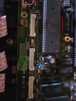
I saw that clock display are powered by this 3 white connectors...it's possible check voltages here maybe?
Thanks!
20200202_122000.jpg
 
Hi.

>>> HI Daver2 how are you??

I am fine thank you. The sky hasn’t fallen down now we have left the E.U.!

Yes, you can measure some of the voltages on the connectors you have identified.

With your multimeter set to AC Volts (say something like 10 Volt range), tell me what you read between connector CN14 pin 1 and CN14 pin 8. This is the heater supply for the VF display.

With your meter set to DC 40 Volts or so, you should be able to measure -30 Volts across C152 and C184.

You should also be able to read DC +5 Volts between CN15 pin 10 (positive) and CN16 pin 10 (negative).

Dave
 
hi.

>>> hi daver2 how are you??

I am fine thank you. The sky hasn’t fallen down now we have left the e.u.!

Yes, you can measure some of the voltages on the connectors you have identified.

With your multimeter set to ac volts (say something like 10 volt range), tell me what you read between connector cn14 pin 1 and cn14 pin 8. This is the heater supply for the vf display.

With your meter set to dc 40 volts or so, you should be able to measure -30 volts across c152 and c184.

You should also be able to read dc +5 volts between cn15 pin 10 (positive) and cn16 pin 10 (negative).

Dave

cn14 pin1=5,5 acv
cn14 pin8=1,6 acv
c152=-00.5v
c184=-00.4v
cn15 pin 10=5.13v
cn16 pin 10= 0v
 
I think a few errors have crept in between us I am afraid...

Let’s take this one step at a time.

With your multimeter set to read AC Volts, can you put one lead of the multimeter on CN14 pin 1 and the other lead of the multimeter on CN15 pin 8 and read the voltage between the specified pins please.

Dave

Ok im sorry for mistakes Daver..
so i read this:
CN14 PIN1 TO CN15 PIN8=0V
 
Looks like the inverter for the display may be non operational.

Can you measure the DC voltage across C84 (100 uF capacitor) please?

Dave
 
Excellent.

So, back in post #7 you measured 5.5 VAC on CN14 pin 1 and 1.6 VAC on CN14 pin 8.

What were you measuring these voltages with respect to (i.e. where was the other lead of the multimeter when you were taking the measurements)? It is interesting we are seeing some AC voltages here... Can you remeasure these points please.

If there are some AC voltages here, where are they going when we take our next measurement I wonder?

Can you remeasure the voltage between CN14 pin 1 and CN15 pin 8 again please? Taking particular notice that you have the meter set to AC Volts.

Dave

Hi DAver2,
i measured with black lead of multimeter on a ground point on the mainboard....in the screw's hole..now i try to put black lead in a gnd cable.
Ok i remeasure:
CN14 PIN1= 5,5v
CN14 PIN8= 1,6V

C14 PIN1 TO C15 PIN8= 0V AC :(
 
OK. Consistent with your last readings - but confusing nonetheless...

Can you try something else for me please?

Can you measure (again, on AC Volts) between GND/0V and CN15 pin 8 please?

Cheers.

Dave
 
Can you also let me know what make and model the VF display is please. I can then lookup the filament voltage specification on the datasheet. I will have a look ion the technical manual in parallel.

It's a Noritake CPF2423A - and I can't find any data on it (on a quick search at any rate).

Dave
 
Can you also let me know what make and model the VF display is please. I can then lookup the filament voltage specification on the datasheet. I will have a look ion the technical manual in parallel.

It's a Noritake CPF2423A - and I can't find any data on it (on a quick search at any rate).

Dave

Ok so
gnd to CN15 PIN8= 5,9V

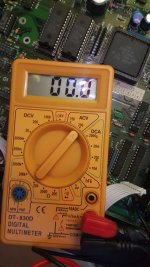
20200203_212513.jpg
 
Curiouser and curiouser...

Just a check that your meter is set to read AC volts and not DC volts...

If this is correct, we are getting GND to CN14 pin 1 (VF2) = 5.5 Volts AC; and GND to CN15 pin 8 (VF1) = 5.9 Volts AC.

However, when we read between CN14 pin 1 and CN15 pin 8 we are getting 0 Volts AC. The only conclusion I can come to at the moment is that the two voltages are exactly in anti-phase and are cancelling each other out...

Dave


Daver2 im unlucky man :(
Every damage in my machines are always very strange :(
I confirm that i use VAC in my multimeter....set as in picture....
20200203_220422.jpg
 
Hmmmm!

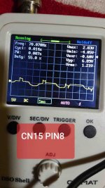
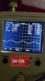
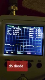
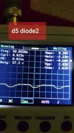
It's probably worth getting the oscilloscope out and measuring the waveform at CN14 pin 1, CN15 pin 8, the collector of transistor Q8 (2SD789 where it connects to transformer T1), and the waveform at both sides of diode D5.

All waveform readings with respect to GND/0V.

Post the results please.

You probably want the oscilloscope set to something like 5 or 10 Volts per division (Y). I am expecting these waveforms to be oscillating (if the power supply is working that is) - so you may have to play with the horizontal timebase to find out what the frequency is. All of the signals may be DC of course - indicating that the oscillator is not working!

Dave
 
Hi Daver2,
W Brexit and W English People!!!I hope this also in Italy ;)

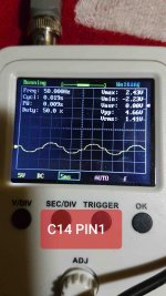
So these are my measure with scope:
20200204_203645.jpg
20200204_203759.jpg
20200204_203947.jpg
20200204_204222.jpg
20200204_204258.jpg
 
Back
Top