Upcoming Events:
- VCF South West - June 14 - 16, Davidson-Gundy Alumni Center at University of Texas at Dallas
- VCF West - Aug 2 - 3, Computer History Museum, Mountain View, CA
- VCF Midwest - Sept 7 - 8 2024, Schaumburg, IL
- VCF SoCal - Mid February 2025, Location TBD, Southern CA
- VCF East - April 2025, Infoage Museum, Wall NJ
-
Please review our updated Terms and Rules here
You are using an out of date browser. It may not display this or other websites correctly.
You should upgrade or use an alternative browser.
You should upgrade or use an alternative browser.
Amiga cdtv 1000 not working
- Thread starter Desperado
- Start date
daver2
10k Member
Yes, they are strange...
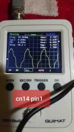
The first one CN14 pin 1 (50 Hz) is just random mains noise pickup. Try reducing the voltage/division from 5 V/div to 1 V/div and reducing the timebase from 5 ms/div to 1 ms/div or even lower (100 us/div) etc. and see if that makes any difference. I would be expecting a much higher frequency than 50 Hz.
Also, the fact that you get different readings on CN14 pin 1 and CN15 pin 8 (two ends of a transformer winding) makes me also think that all is not well.
I can't find any datasheet on the VF display itself. It was probably a Commodore special that was made.
Dave
Desperado
Veteran Member
- Joined
- Nov 25, 2017
- Messages
- 6,827
Yes, they are strange...
The first one CN14 pin 1 (50 Hz) is just random mains noise pickup. Try reducing the voltage/division from 5 V/div to 1 V/div and reducing the timebase from 5 ms/div to 1 ms/div or even lower (100 us/div) etc. and see if that makes any difference. I would be expecting a much higher frequency than 50 Hz.
Also, the fact that you get different readings on CN14 pin 1 and CN15 pin 8 (two ends of a transformer winding) makes me also think that all is not well.
I can't find any datasheet on the VF display itself. It was probably a Commodore special that was made.
Dave
Ok Daver2,
this is new measure on C14 Pin1
Do you think that T1 it's broke maybe?

daver2
10k Member
I assume that you are testing this without the display being connected?
Before assuming that it is the unobtanium transformer (!) there are a number of other components around the transformer that it could be first.
For example, remove and test transistors Q7 and Q8.
With these transistors out of circuit, you can check the transformer primary is OK by measuring the resistance from Q7 collector to Q8 collector (again, with the two transistors out of circuit). A low resistance is good. An open circuit is bad.
Check capacitor C85 for short circuits.
Check capacitor C86 for short circuits. Do you have a capacitor tester? If so, check its value (680 pF).
Check diodes D3, D4 and D5. D3 and D4 are zeners. D4 is 5.1 Volts whilst D3 is 31.5 Volts.
The only thing left to check are a couple of resistors (R71 and R72).
You should also check the transformer secondary windings by checking the resistance from Q8 emitter to the junction of R72 and D5; and from CN15 pin 8 to CN14 pin 1; and from CN15 pin 8 to the positive end of C85; and from CN14 pin 1 to the positive end of C85.
Hope this all makes sense?
Dave
Desperado
Veteran Member
- Joined
- Nov 25, 2017
- Messages
- 6,827
Good evening Daver,
i removed q7 and q8 but they seems to be ok...i tried (without q7 and q8) resistance from Q8 centre pin to Q7 left pin and i read 0,05 ohm and not open circuit...
Now i must check capacitors but i don't have capacitors tester
i removed q7 and q8 but they seems to be ok...i tried (without q7 and q8) resistance from Q8 centre pin to Q7 left pin and i read 0,05 ohm and not open circuit...
Now i must check capacitors but i don't have capacitors tester
daver2
10k Member
Just check with your multimeter set to resistance that there are no short circuits on the capacitors.
A low-valued capacitor should appear as an open circuit. High(er)-valued capacitors will initially appear as a low resistance, but they will “charge up” over a period of time and the resistance should increase.
Dave
A low-valued capacitor should appear as an open circuit. High(er)-valued capacitors will initially appear as a low resistance, but they will “charge up” over a period of time and the resistance should increase.
Dave
Desperado
Veteran Member
- Joined
- Nov 25, 2017
- Messages
- 6,827
"Check capacitor C85 for short circuits.
Check capacitor C86 for short circuits. Do you have a capacitor tester? If so, check its value (680 pF).
Check diodes D3, D4 and D5. D3 and D4 are zeners. D4 is 5.1 Volts whilst D3 is 31.5 Volts.
The only thing left to check are a couple of resistors (R71 and R72).
You should also check the transformer secondary windings by checking the resistance from Q8 emitter to the junction of R72 and D5; and from CN15 pin 8 to CN14 pin 1; and from CN15 pin 8 to the positive end of C85; and from CN14 pin 1 to the positive end of C85."
Daver2, i do all this but seems to be ok....
daver2
10k Member
No, it can’t be the fault - as we are trying to work out where the power supply has gone for the display. This is the display controller (I assume) and has nothing to do with the power supply.
Back to basics:
1. The VFD display is not connected to CN14 and CN15 when you are taking the measurements?
2. It looks like all of the components in the power supply unit are working?
3. The power supply unit has +5 Volts fed to it? Voltage across C84.
4. All the components are back in the power supply?
5. Do we get Volts or not?
The data sheet for a random Noritake VFD indicates that the heater supply should probably be oscillating between 10 kHz and 200 kHz. Have you set your oscilloscope timebase accordingly to see this sort of frequency? In the previous posts it was always set to 5 ms. At this value you will never see these high frequency oscillations.
Dave
daver2
10k Member
Item 2 - yes, the components you are referring to.
Item 5 - at this point I am not actually interested in whether the display works or not. I am interested in where the Volts are to power the display in the first place (in this case the heater voltage and the anode Voltage). There may be other issues preventing the display from working, but we have to tackle them one at a time and in the correct order.
The question I am trying to answer is “if we have +5V fed to the inverter, and all of the individual components are working, why are we not getting the correct voltages”?
Did you have a go at my last paragraph from post #29 or not?
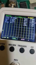
I am surprised we are getting a significant amount of 50 Hz (from your image posts of the oscilloscope traces) so either the oscillator is working at 50 Hz (unlikely) or the oscilloscope is not connected to 0V/GND well. I did see signs of “little pulses” superimposed on the 50 Hz wave in one of the heater voltage traces - so something is trying to work...
Dave
daver2
10k Member
The measurement points are back in post #19.
I don’t see any point in doing anything else until we get the display power supply inverter working.
Post #19 contains the locations to scope (as you have done previously) we just need to ensure you have a good 0V/GND reference for the oscilloscope and play with the horizontal timebase settings.
We need to work out where the 50 Hz is coming from and see if we have a problem with the setting of the timebase to see the oscillations we are looking for.
Dave
Desperado
Veteran Member
- Joined
- Nov 25, 2017
- Messages
- 6,827
The measurement points are back in post #19.
I don’t see any point in doing anything else until we get the display power supply inverter working.
Post #19 contains the locations to scope (as you have done previously) we just need to ensure you have a good 0V/GND reference for the oscilloscope and play with the horizontal timebase settings.
We need to work out where the 50 Hz is coming from and see if we have a problem with the setting of the timebase to see the oscillations we are looking for.
Dave
So i re measured CN14 pin 1 with some v/div but nothing changes....i can see always 50hz

daver2
10k Member
I am not talking about the vertical v/div but the horizontal timebase ms/div or us/div...
Dave
Dave
Desperado
Veteran Member
- Joined
- Nov 25, 2017
- Messages
- 6,827
I am not talking about the vertical v/div but the horizontal timebase ms/div or us/div...
Dave
Nothing also with any ms/div setting....i see always 50 hz or lower freq...
daver2
10k Member
Ok,
So back to the multimeter on dc Volts (10 Volt range) with the black lead connected to 0V/GND for all measurements.
Measure the voltage at the following points:
Junction of R71 and Q7b.
Junction of Q7e and Q8b.
Q8c.
Dave
So back to the multimeter on dc Volts (10 Volt range) with the black lead connected to 0V/GND for all measurements.
Measure the voltage at the following points:
Junction of R71 and Q7b.
Junction of Q7e and Q8b.
Q8c.
Dave
Desperado
Veteran Member
- Joined
- Nov 25, 2017
- Messages
- 6,827
Ok,
So back to the multimeter on dc Volts (10 Volt range) with the black lead connected to 0V/GND for all measurements.
Measure the voltage at the following points:
Junction of R71 and Q7b.
Junction of Q7e and Q8b.
Q8c.
Dave
Junction of R71 and Q7b=1,6V
Junction of Q7e and Q8b=4,5V
Q8C=5,10V
daver2
10k Member
Ah,
With a high positive voltage on Q8b (and Q8e connected to 0V) then Q8 should be fully turned on and (therefore) Q8c should be 0.7 Volts or so. Have you got a faulty Q8?
Dave
With a high positive voltage on Q8b (and Q8e connected to 0V) then Q8 should be fully turned on and (therefore) Q8c should be 0.7 Volts or so. Have you got a faulty Q8?
Dave

