• Please review our updated Terms and Rules here

Amiga cdtv 1000 not working

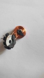
That appears to be pin 7 that has broken off not pin 9?

Can you still see the wire that would have been attached to the pin?

Zero Ohms is just too low (in my opinion) for the winding resistance from pins 2 to 3.

With the transformer out of circuit, can you repeat the same test that we did back in post #92 to see if the primary winding is actually doing what it is supposed to be doing.

Dave
 
Oh...

Is it possible to identify which of the wires did go to which of the pins of the transformer?

It is still potentially repairable (again, if the winding is OK).

Dave
Dave
 
I prefer buy a new one.....too difficult for me repair this little wires...
where i can find this t1 Daver?
 
There is a Commodore part number of 200966-02 in the service manual, but a quick check on google doesn't throw up any useful links (other than the service manual itself)!

Dave
 
There is a Commodore part number of 200966-02 in the service manual, but a quick check on google doesn't throw up any useful links (other than the service manual itself)!

Dave


unfortunately I read on some forums that it is a component that is not found .... they say that it should be taken from other boards sold as a spare :(
 
Which is why I am saying that with a bit of careful work it may be possible to save the transformer - providing it is actually working - which I think it may not be (hence the reason we removed it in the first place).

If it is not working; it may be possible to unwind the transformer (counting the turns of wire as you go) and rewind it (once purchasing the correct diameter of enamelled copper wire).

Dave

Too difficult for me...i can try to search if someone can sell me one of this...
 
We know what Vpp is - it is -30 Volts (taken from page 5-1 of https://archive.org/details/CDTV_Service_Manual_1991-05_Commodore/page/n13/mode/1up).

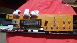
But I have no idea what the filament voltage (Vf) is for correct operation of the display. That is not specified anywhere within the service manual. Is it marked on the VFD display by any chance?

Too much voltage on the heaters will damage the display - and that is completely unrepairable.

Dave

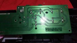
I can't see any voltage marked on display :(
20200216_165713.jpg,20200216_165726.jpg
 
We know what Vpp is - it is -30 Volts (taken from page 5-1 of https://archive.org/details/CDTV_Service_Manual_1991-05_Commodore/page/n13/mode/1up).

But I have no idea what the filament voltage (Vf) is for correct operation of the display. That is not specified anywhere within the service manual. Is it marked on the VFD display by any chance?

Too much voltage on the heaters will damage the display - and that is completely unrepairable.

Dave

Hi Daver,
can this post be useful maybe?
http://eab.abime.net/showthread.php?t=55269
 
That post is interesting, but I don’t believe what is posted for one second...

There is no way the heaters are 31.5 Volts (this is higher than Vpp for a start).

Also, the heaters are not dc they are ac.

Do you know of anyone (or can find someone) with a working machine who would be willing to measure the voltages? You could then purchase something against this specification.

Dave
 
Your picture of T1 back in post #45 doesn’t look the same as the photograph you have linked to.

Your photograph appears to be missing the outer ferrite ‘cover’. Did your T1 ever have this?

If not, the operation of the inverter will be seriously impaired.

Dave
 
Your picture of T1 back in post #45 doesn’t look the same as the photograph you have linked to.

Your photograph appears to be missing the outer ferrite ‘cover’. Did your T1 ever have this?

If not, the operation of the inverter will be seriously impaired.

Dave

No Daver, when i opened for first time the Cdtv, i haven't see ferrite cover on T1!!
 
Back
Top