nikola-wan
Veteran Member
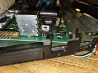
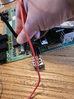
BTW - I powered up my Bally Computer System and the VRs are working but I have no video out of the RF Modulator.
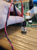
I even unplugged the RF Modulator and connected pin 1 of J1 (farthest away from the Line Filter) and ground to an RCA video cable to my little Sony TV and had no video.
According to the Bally forum - that is a common problem. I think I will need to build the Balcheck board or the SetScreen board to diagnose.
Last edited:
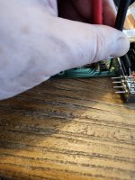
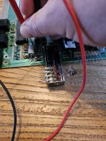
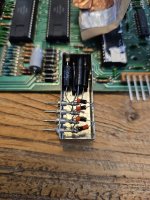
") I was reading through some troubleshooting docs and they mention checking the transistor over there in case that is shorted..
I was reading through some troubleshooting docs and they mention checking the transistor over there in case that is shorted..