• Please review our updated Terms and Rules here

Cannot use EPROM to replace character ROM in 4032.

A4000Bear

Experienced Member
Joined
Dec 30, 2010
Messages
111
Location
Taradale, VIC, Australia
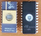
I was attempting to replace the character ROM with an EPROM in my 4032, and every attempt results in corrupt characters or screen layout. The severity depends on what brand of EPROM I use, and is consistent within different EPROMS of the same brand/type. For example, using any 2716 made by ST results in the entire screen shifted one character to the left, the leftmost character is now on the right of the screen. Disregard the two lines of odd characters, they were the point of attempting to change the character ROM.
322488815_844410190004432_5609990882301844544_n.jpg

Other EPROMS gave even worse results.

In an attempt to isolate the problem, I tried reading the existing character ROM, and then burning its contents to various different brands of 2716 as well as several TI 2516s. All failed. All these EPROMs burn correctly and all pass the programmer's verify test. I should also point out the 4032 works perfectly with the original character ROM, and that I have previously sucessfully used EPROMS when replacing other ROMs in that machine.

A quick check on all the pins with an oscilloscope didn't reveal any obvious problems, however, a closer look revealed this on pin 10 (D1).
pic_70_4.jpg

Replacing the original (working) Commodore ROM gives this:
pic_70_5.jpg

Other data pins also have these spurious pulses when an EPROM is used. Sometimes these pulses are only 2 volts, but most of the time they are a bit over 4V. As you would expect, with EPROMs that have more corruption, there are more of these extra pulses. Power in the 4032 is at 5V and is clean.

Has anyone successfully used an EPROM to replace the character ROM in their 4032?
 
Does the OE_n or CE_n pin of the EPROM go high at the same time as these pulses? If so then the EPROM's outputs are disabled and getting pulled high during this short period. The Commodore either does not have these output enable pins so always stays enabled, or is much slower than the EPROM and de-asserting then re-asserrting the enable(s) quickly does not result in the bus going hi-Z.

If you get different results between different EPROMs then it is possibly a speed issue...

Also could be that the EPROMs are so fast that any slight change in the address signals will immediately result in new data presented at the output. Again, the Commodore ROM may be slower and not reacting to the quickly changing address lines. From the look of the waveform I would guess the EPROM is around 100ns or faster. The Commodore ROM could be three times slower...
 
Last edited:
Sometimes these pulses are only 2 volts,
So the pulses dont get to full voltage? Then it is most likely a speed issue.. The EPROMs, which are likely much faster than the Commodore's ROM, are reacting quickly to the address lines changing and responding with the data contents for these intermediate addresses...

Or EPROMs are so fast that they are violating the circuit's expected hold time.
 
Last edited:
So the pulses dont get to full voltage? Then it is most likely a speed issue.. The EPROMs, which are likely much faster than the Commodore's ROM, are reacting quickly to the address lines changing and responding with the data contents for these intermediate addresses...

Or EPROMs are so fast that they are violating the circuit's expected hold time.
Was going to suggest the same - are the EPROMS you are burning the same speed as the original?
 
Hmmm..........interesting.

When I was working on my Dynamic 20001 PET boards, I prepared a full set of replacement UvEproms with known good data.

They were all NOS TMS2532JL types, except for the Character ROM and the Edit ROM, which were required to be different; both 2716 types. (I used vintage mil spec Czech UVEproms that I imported from Europe, as they had the reputation of being super quality and they had lovely gold & ceramic packages)

In any case I found something very interesting, comparing the the original PET character ROM with the 2717 UvEprom.

Pin 21 of the original character ROM socket connection, labelled CS3, is connected to the /INIT pull up line in the computer. While this successfully pulled up to logic high, with the original mask, or pre-programmed ROM that the PET was supplied with, it did not quite make it properly with the 2716 UvEprom, as the sink current on that pin 21, was higher with the 2716. Why this is the case I am not sure.

So one option is, without modifying the computer at all, if you don't have the original PET character ROM, is to bend the pin 23 of the substitute 2716 IC out of its socket and tie it directly high to +5V

(it is probably not a good idea to mess with the /INIT pull-up line itself as it can have some interesting effects on boot up and it affects the 4 state machine too).

I'm not sure if it relates to your computer at all, but worth checking.
 
Yes, a 2716 should be OK.

As has already been mentioned speed could be an issue - are the devices fast enough.

Also (as @Hugo Holden has mentioned) is the issue regarding pin 21 (Vpp) - not pin 23 as Hugo described though. Vpp is a power rail not a signal level - so should be 'hard tied' to Vcc.

Incidentally, you will observe 'garbage pulses' on the data lines of the character generator as the address lines change state from one character to another. All of the active low chip selects are permanently grounded (so the character generator is permanently enabled).

Dave
 
For example, using any 2716 made by ST results in the entire screen shifted one character to the left, the leftmost character is now on the right of the screen

This is an utterly baffling symptom. The character ROM is completely isolated from anything video addressing related other than the row outputs from the CRTC, how on earth could it be causing this bizarre off-by-one line alignment problem?

Are you sure your CRTC isn’t bad?
 
Don't forget that the data outputs from the character generator are latched into the parallel to serial shift register, so any timing issue before the shift register will result in a single character delay due to the load pulse of the register.

The key timing is signal VIDEO LATCH that latches the output from the video RAM into the address lines of the character generator ROM and /LOAD SR that latches the data from the character generator ROM into the video shift register.

Is it also possible that the EPROMs you are using are too fast as opposed to too slow?! The reason I am asking is that we had a similar "off by one" issue on a NASCOM 1 computer - and this was all down to the speed of a particular device in the divider chain. It needed to be a "goldilocks" device - not too fast and not too slow, but just right!

What does your video screen look like? Can you post a photograph? Is it missing a character on the left-hand side, or is it shifted to the right by a character? EDIT: Ignore this! I see you are missing a character from the photograph in your first post... Read first, post second!

Dave
 
Last edited:
Don't forget that the data outputs from the character generator are latched into the parallel to serial shift register, so any timing issue before the shift register will result in a single character delay due to the load pulse of the register.

The characters don’t appear “delayed”, in the photo it’s the opposite, all characters are offset forward one position. Again, I don’t see how a change in the character generator could possibly cause this? The data it’s translating comes from the latch, so in any sensible design the contents of said latch should be stable until *after* the LOAD_SR signal. For this to be the result of a “too fast” ROM would imply that the video circuitry is always already asserting “Currently to-be-latched character cell + 1”’s address on the video memory bus *and* is dumb enough to open the latch simultaneously with SR_LOAD, so the only chance you‘d ever get the correct dots loaded into the shift register relies on how slowly the original ROM responds to address bus changes.

… I mean, really, is that how it’s set up?

Is it possible the latch is broken/always open? (IE, it’s always transparent, so that thing I said about the ROM address propagation delay *is* the only thing saving it, but it’s not supposed to be? The problem I see with that theory is I’d think CPU accesses would then constantly be shuffling the video address visible through the unlatched latch as well?)
 
It is interesting, just to confirm:

1) the original ROM is fine
2) only the ST 2716 copies play up
3) that the copies and the original verify as equal in the programmer.

It does suggest it is the ST 2716 having a timing difference, even though it would appear as Eudi points out that really the circuit should not be sensitive to this. And as Daver2 mentions it could be a case of the "Goldilocks" effect, though it could be that two of the porridge options work and the other doesn't.

There is this thing though:

I could take a photo, but I think that IC die size in the ST 2716 part is much smaller compared to the Czech mil spec 2716's IC's I used. I noticed this when I bought batches of 2716's for testing, for this reason I didn't use the ST parts, because they sort of looked like modern clones.

The very large IC die means it has much higher capacitances and everything changes state at a lower speed. So if it is a timing issue, the ST 2716 is likely much faster and it does appear transients are appearing.

Or it could be that some other borderline timing condition is conspiring with the problem.

I would definitely try to find some NOS 2716's and go for ones with the large die in them, at least it is easy to see that through the window.

With the pin 23 & /INIT line, that line does connect to a good number of IC's in the clock & timing generation circuits, so odd things could happen if it got pulled to a near indeterminate logic state for some IC's and not others. You could try, after the computer has started, to connect a 1k resistor from pin 23 to +5V and see if it had any effect. In my computer, the dragging down of the /INIT line by the 2716 caused vertical drive pulse and vertical scan instability. Due to the small amount of + feedback in the V scan stages in the 9" VDU, it made the image oscillate up and down vertically.
 
Last edited:
can you post a pic of your motherboard. I too found an identical issue when working with the Supersoft HR board which has its EPROM based character rom … it appeared dependant on the version of universal board ….never got to the bottom of it but discussing with Steve G, at the time, maybe down to a timing issue.
 
Last edited:
The OP says that it works fine with the original character generator ROM, so that should rule out logic problems.

If the EPROM is too fast?

Dave
 
I have attached a photo.

When I saw the tiny die in the ST 2716, I rejected using them in my PET. It is one of those problems I am sort of used to, with modern clones of transistors.

I first ran into trouble with this effect in some vintage DC/DC converters that used the 2N3055. The more recent manufacture ones had a die in them that was about 1/4 the surface area of the original part. One could argue that it improved the part from the high frequency perspective, but it became unstable, in the particular circuit, and the newer ones caused the circuit to burst into parasitic RF oscillation due to the transformer's leakage reactance. I had to force their frequency response lower with added base to collector feedback capacitors. So when I see small dies, compared to original parts, it puts me off them.

UV eproms are one of the few parts where you can see the die and I would bet that the ST part with the tiny die has a much faster response, because the capacitances are lower everywhere in the structure. It doesn't mean it is an inferior part though, or doesn't "work", one could argue better in that respect, but it might not suit a Goldilocks circuit as Daver2 mentioned.

Some circuits play up with memory IC's and timing anomalies. For example, I mentioned on another thread that I had bought a 4116 DRAM tester, it reported that 20 NOS 4116-15nl chips were defective. But they all worked fine in the PET, somehow, the tester was fooled by the faster part, but assessed the slower ones normally.
 

Attachments

  • 2716dies.jpg
    2716dies.jpg
    142 KB · Views: 4
Haven't heard from the OP so maybe they already discovered the issue - But despite the glitches it looks like the character ROM is working fine. The problem seems to be elsewhere in the circuit.

If you notice, the first character seems to be a row above the rest of the text. The 'R' in Ready is one row above the EADY and there is a missing asterisk surrounding Comodore BASIC at the top left of the screen. It appears that the "origin" of the video buffer is off by one character.

Not sure what would cause this, but after this shift everything appears to be ok as far as displaying the characters. Hard to point to the character ROM/EPROM as having anything to do with this.

I wonder if this shifting is a one-time (boot-up) occurrence and if you enter the command to clear the screen that it will re-establish the video buffer at the correct "origin" and the screen will be corrected.

Speculating further - if this is a one-time (boot-up) occurrence and if it really is related to the EPROM, then perhaps it is a voltage-dip, or SSO, or ground bounce issue where the EPROM glitches the video circuit due to its speed in a way that the slower Commodore ROM does not. I assume the EPROMS's rising/falling edges are much faster so maybe causing power to dip(?)

This could well be the case, since when I was investigating the /INIT pull up line in my PET (see why below *) I found if it was altered even by lowering the pull up resistor value, it caused boot up anomalies. So this could well be happening with pin 23 (edit Pin 21 not 23) of the 2716 loading the /INIT line and the original ROM not doing that.

* = the reason why I was investigating the /INIT pull up line in my PET was; I was trying to discover how it was that the 4 state machine did not get out of step at the initial boot up.

With the power dip issue maybe the OP could try a 0.1uF cap across the rom's power pins and see if that had any effect.
 
Last edited:
Could also try this:
SHIFT+CLR/HOME Clears screen and places cursor in "Home" position
 
Back
Top