• Please review our updated Terms and Rules here

CBM Pet 4032 DOA

mjnurney

Experienced Member
Joined
May 13, 2015
Messages
199
Location
UK
hello all, my first post ...be gentle.

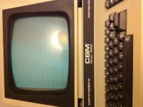
Im after some help on a dead 4032 PET

here are some details...


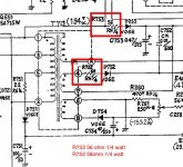
I've ordered some sockets for chip removal and ram tested (all soldered) I'm slightly conviced the PSU is outputting wrong ....ive ordered new regs to solve this i hope.

the 12v /5v is too high and the -5 is too low


I've also ordered the PETvet board to help with diagnosis.

mike

RAM 4116 pin1=-6.3v pin8=15.8v Pin9=6.45v Pin16=GND

Video ram - swapped for ZX ram - seems good.

CPU - tested good.

motherboard to monitor
white=0
grn=6.39
white=0
red=5.88
w=0
yell=2.3

AC PSU


BL=13.55
BL=13.55
BLK=0
BWN=12.2
RED=0.44
BWN=12 OR 7 OR 3 (cycles)

CPU pin 8 =6.34v

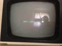
The monitor occasionally has a light from the centre or a straight line top to bottom about 1mm wide and then fades to black , no beep from the buzzer on the pet.

I think something odd is going on with the PSU but I'm having trouble finding what they should be.


ive done some work since with a new multimeter and the outputs look better , I've list them in a reply below but I'm waiting for moderation? Anyway - Power looks ok , i have changed the CRT controller and now the PET seems to be pulsing like its stuck in a loop ? ....

BLUE/BLUE 16.62-16.64
BRWN/BRWN 18.41-18.42 AC

RAM -4.89, 11.83, 5.06 volts

Video connector now has pulse , voltages are yel:1.53, White 0,Orange 4.58, White 0,green 4.80 (white is ground?)

cpu pin 8 = 5.02v

I video'd the noise that the screen makes , no picture obviously

https://www.youtube.com/watch?v=x6cqniWV4gc


mike.
 
Last edited:
motherboard to monitor
white=0
grn=6.39
white=0
red=5.88
w=0
yell=2.3

AC PSU


BL=13.55
BL=13.55
BLK=0
BWN=12.2
RED=0.44
BWN=12 OR 7 OR 3 (cycles)

CPU pin 8 =6.34v

First the power supply AC signals in transformer secondary:
Across the blue wires should be: 18VAC
Across the brown wires : 22VAC

Is the transformer making a lot of noise?
What kind of voltmeter are you using? Check calibration with a 9V battery. If off, replace batteries in meter.
The input to the +5V regulator VR4 should be +9V unregulated (some AC ripple). If excessive ripple, replace big capacitor C1.
If Vcc is really at 6.3VDC then it is bad for the ICs, but hard to believe regulator output is at 6.3VDC.

As for the video connector, it appears the pin 5 Horizontal Drive is not pulsing (pin 6 is empty key). That will not allow high voltage to CRT. Disconnect video connector to monitor until power and video timing signals are correct to protect the CRT.
 
thanks

i'll take a look in a minute , there is no noise from the transformer and its a cheapo multimeter my better one is at work. ill check VR4

cheers
 
okay some readings with a better multimeter and a new battery this time and the voltages look better thankfully.

AC
BL 16.62 to 16.64
BWN 18.41 to 18.42

motherboard video pinout

yellow=1.53
white= gnd?
orange=4.58
white=gnd
green=4.8
key
white=gnd

VR1=4.98 / 12.31

VR2/3/4
5.75v
5.81v
9.71v

cpu pin8 5.02v
ram 4116 -4.98 , 11.83 , 5.06v

Would the screen remain blank if the CRT controller chip had died ? most other faults except cpu would display something - provided the CRT works that is. Is it possible to feed another signal in to the monitor to test it ? i.e a C64 or similar.

Ive never seen this PET work. it was last used in the early 80s by a guy who designed add on cards for Apple in the UK and in doing this he made things for the PET but he's an old guy now and mostly blind so i bought this from his niece, id like to get it running :)
 
I've changed the CRT control chip and now the monitor makes a pulsing noise - quiet but its a noise.

I now have two pulse signals on the motherboard header for the monitor.

No picture on screen or chirp from the motherboard yet but its progress i suppose. A picture on screen would be handy to see whats going on with the PET.

mike.
 
+1 for Dave's suggestions.

Disconnect the monitor from the main board and put it's connector in a small plastic bag to stop it shorting out anywhere.

I would be inclined to disconnect the transformer from the main board until we have ascertained if the transformer is faulty or not. Over-voltaging the semiconductors is not a good idea (if it is not too late)!

One really daft idea (!) I assume the transformer is wired for 230/240 V rather than 110/115?

As Dave has suggested - use a multimeter set to AC Volts and measure the secondary voltages directly from the transformer to ensure they are in specification. If these are OK - I would next check the bridge rectifier diodes with the low resistance setting of the multimeter (again - with the transformer disconnected) and then (if these were OK) - go ahead and replace the voltage regulators.

It is weird that the +5, +12 AND -5 regulators are all duff though (unless something else has killed them)...

If you are in the 'replacing' mood - I would probably replace the large power supply smoothing capacitor as a matter of course if you plan to keep the PET - this will probably only cause you grief in the future if you don't.

Dave
 
Hi thanks for the info , now I have a better multimeter I think the psu is ok ? Voltages look good 5.0v on the motherboard. The noise I can hear from the crt is I think the pet either not making it to boot or resetting constantly ... Just a guess of course I need to get the oscilloscope out
 
Would ROMs give a similar fault to this ? i may burn some Eproms and see how i get on , all logic chips can be changed easily enough but the commodore specific chips i'll need to burn or replace. Its a shame i can't get a picture to help with the fault.

changed so far

2116 ram
6502 cpu
CRT controller
i/o chips removed x2

Suspect parts

Roms
main Ram


mike.
 
Anyway - Power looks ok , i have changed the CRT controller and now the PET seems to be pulsing like its stuck in a loop ? ....


Mike,
Pet seems to be stuck in a loop? What you referring to?

If you do not get a beep, the system is not running in program. That is usually caused by a bad upper ROM from D000- FFFF. One of these 3 chips may be bad. Also one of the eight RAM chips needed for low RAM (0 to 16K) may be bad. Any of those on sockets? Are the two PIAs and VIA on sockets?
 
I just mean the Pet is pulsing almost as tho its being reset, however its not.

The cpu line is high after 1 second and the cpu functions fine.

The crt controller, i had in , I've taken out and put another in but this functions the same as the original - i.e nothing much.

PIA's removed , VIA replaced
all 4116 ram now socketed and changed for new old stock

but nothing , chips and board get slightly warm to the touch after being on for a while but nothing much. Screen remains blank and no chirp sound at power on.

How can i tell if the TLL chips have failed without changing everyone? everywhere on the board there are LS chips ....of course the ROMs I've burnt may be at fault but they read perfectly in the programmer.

Ive tested the capacitors too , unsoldered them and they are above or within the original spec, i have emailed bit fixer about the PETvet but no response from him at the moment.

Is there no way to get something on screen ? no diagnostic program available?


im not sure if i can answer any of your questions , my replies are stopped for moderation
 
Last edited:
hello,

maybe this gets thru moderation :)

With one CRT controller chip it , the monitor seems to pulse like a reset but its not i don't think. i have another CRT chip now and it behaves the same as the original one. I youtubed the pulsing one.

Anyway

i have socketed all the ram - no change with new ram
all roms burnt with eproms - no change
pettest.bin burnt - no change
capacitors tested all good.
video ram socketed - all good
cpu= good
PLA=good
VIA = 2x removed
voltages seem good too from PSU
reset line high on cpu after 1 second.

just a blank screen ...im puzzled

just checking the CPU voltages

pin 9 to 25 3.64v
pin 26 0.21v

is this normal , checking the schematics..


Thanks Dave , i cannot answer you properly as my messages are moderated and don't appear for a few days - why??

- very annoying


Anyway it was the pettest 2 that i burnt , I've tried the 50hz version but nothing ...so something else is very wrong. i don't even know if the screen works.
 
Last edited:
Some progress , I've stripped and cleaned the CRT and on inspection a resistor had blown. Its raised from the board so i expect its supposed to blow under certain circumstances anyway I've replaced it and now i kind of get a picture on screen.

when powered off the screen has a dot in the middle for a second or two as you would expect.

I have 3 CRT chips

1 x HD46505 makes a rectangular box on screen

1x HD46505 just pulse the screen

1x MOS 6545 does nothing.

Now the pet tester rom (kernel) dent do anything at all. I'm wondering if the RAM is being accessed at all?
 
Great news I've finally got it booting up - chirping away happily

the faults were :

Bad kernal ROM
broken track 17 from editor rom to next rom (basic)
blown resistor in the CRT


so plenty really - however i now have lines across the screen rather than the commodore basic logo. - i hope this isn't a bad CRT - however i fitted a 52ohm resistor as its all i had -so that could be the fault here

still ...its progress , yay

it doesn't seem to like pettest , i'll burn it again i think

all other original rom are ok

mike.

Work done.

All sockets changed
RAM removed and socketed
all roms removed and socketed
resistor changed in CRT
crtc controller changed
all roms burnt on eprom

@Administartor - thank you for allowing my posts to be unmoderated now.
 

Attachments

  • bad roms.jpg
    bad roms.jpg
    41.6 KB · Views: 3
  • working.jpg
    working.jpg
    37.6 KB · Views: 3
  • 4032 CRT.jpg
    4032 CRT.jpg
    89 KB · Views: 3
Last edited:
however i now have lines across the screen rather than the commodore basic logo. - i hope this isn't a bad CRT
Mike,
Great work. You are a good PET Detective.

You are getting a proper raster scan, so the Vertical and Horizontal timing signals are good (good 6545 CRTC). What you are probably not getting is video data to the video board. Lets start with J7-pin1 the Video signal (Pin 6 is the keyway). I wish you had a scope, but on a voltmeter the DC average of the screen with mostly black should be around 0.6V (I think). If you were getting a random garbage screen, the voltage would be close to 2.5 VDC.
-Dave
 
It's not because I changed the resistor for a 52 ohm is it ? I don't have the correct one.

I have a scope but little idea how to use it :)
 
0.40v I've hooked up the silly scope on it too
 

Attachments

  • image.jpg
    image.jpg
    96.5 KB · Views: 1
  • image.jpg
    image.jpg
    96.3 KB · Views: 1
Last edited:
It's not because I changed the resistor for a 52 ohm is it ? I don't have the correct one.

No, that have nothing to do with the video signal. The resistors do act as fuzes to protect the monitor. Using 52 Ohms may take more current than 70 Ohms to cause the resistor to pop so you should replace them with the correct ones when you can.
 
ok thats good to know, so why do you think i have no video signal ?

mike.
 
Back
Top