dave_m
Veteran Member
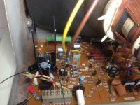
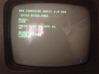
Yes, I agree, replacing the capacitors should fix this, and also the lingering dot in the middle of the screen on power off.
Now ....i have a hunch its power related.
AC PSU -
16.59v
18.35v
A/C to CRT 21.4v
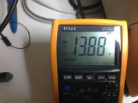
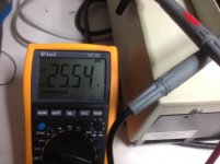
Crt voltages at HTI7818p in 24.8v / out 13.50 / 13.60v
Hi Dave
Output from the 7818 should be 20v ? I'm
Way below that ...
I have a L7818cv here would that replace it ?
Hi Dave
Output from the 7818 should be 20v ? I'm
Way below that ...
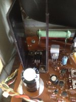
It's OK. There is a full wave rectifier (D901) on the video board that should convert the 22 VAC to an unregulated 22 VDC (DC with ripple). Capacitor C901 smooths (filters) the 22V. This is what goes to the 7818 regulator.something isn't right...
excellent ....i better check that, maybe its killed the reg?
RB151 rectifier
what about amperage and voltage rating?
i can make one from 4 diodes. 1n4007 x4
However if the 7818 is rated to 35v why does it matter that I have 24v input?
1N4007s are rated at 30A so quite a bit of overkill, but they would certainly work. You only need 2A and 25V reverse voltage.
It's not that it wouldn't work, the problem is that with 22 VAC as the input to a rectifier, one can not create 24 VDC out. There must be something wrong with the measurement or ???