• Please review our updated Terms and Rules here

CBM Pet 4032 DOA

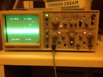
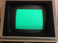
0.40v I've hooked up the silly scope on it too

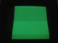
0.4 V seems about right when one has a mostly blank screen. Hook up the 'A' channel of scope and set the scope to trigger on positive edge on the A channel. You should see a burst of 125 nS pulses every screen refresh of 16 mS as the pixels spell out the Commodore message. You may need to turn up the brightness of the trace (intensity) to see the pulses due to the low duty cycle. It is a lot easier to see if there were a lot of data on the screen. If it is too hard to see the data, I may have you pull the Video RAMs to cause a checkerboard pattern and make it easier to see the video data.

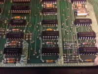
If the video signal is OK at the input to the video board, it may be lost somewhere on the video board. Looking at the schematic, there are only four transistors in the path so it may not be impossible to fix.
 
Last edited:
My scope skills are not very good I'm afraid ...

I'll look tomorrow , sleep time :)

Thanks Dave
 

Attachments

  • image.jpg
    image.jpg
    92 KB · Views: 1
Last edited:
May I ask how you found the dead resister? Can resisters be tested in-circuit?

Also, by "track 17", do you mean pin 17 on the roms?

Thanks for any response,
- Bo
 
May I ask how you found the dead resister? Can resisters be tested in-circuit?

Hi Bo, Mike said he did a physical exam of the video board. It is a known failure mode of the video board. Yes, the resistor can be measured in-circuit (power off) as the parallel resistance looks fairly high.

Also, by "track 17", do you mean pin 17 on the roms?

I also assumed pin 17 on the ROMs. If so, it being D7, the system will not fetch many valid instructions before going south.
 
Last edited:
My scope skills are not very good I'm afraid ...

I can't tell much from that scope photo. Let's not worry about the scope right now. Turn off power and carefully remove the video RAM chips (UC4 and UC5) if on sockets. With opens going to the character generator, we should have a checkerboard pattern on the video data line. See if J7-Pin1 measures about 2.5 VDC.
 
Hi guys

No , with video ram removed it's still 0.4v, with the ram removed and or character rom removed - still the same.

I've just tried fitting a cassette deck to it, the cassette drive powers up for a couple of seconds then nothing.

I wonder if the computer is actually running .. .?chr$(7) does nothing

So does this mean a video signal is not reaching the CRT screen for some reason or is the screen on the blink?

edit.

I've just measured the NPN transistor on the screen and it 0v (i think) 2SC681A


The resistor on the crt board was slightly darker than the others. What drew me to it , was the fact its elevated from the PCB- which i took to mean its expected to blow (fuse?). A multimeter showed open circuit on all ohm Rangers - so it's blown.i tested it in circuit and then unsoldered it and checked again - blown. There are a pair of them , only one was blown the other read 56 ohms , so the one that blew was the 58 ohm one.

I found pin 17 on the Roms by doings a continuity test along all the Roms . In total two tracks were broken under the Roms. I also had a broken pin on the character ROM that was stuck in the socket, i ended up changing the socket and soldering a extension on the ROM.

Rusty sockets don't help on the pet either.

Mike
 
Last edited:
No , with video ram removed it's still 0.4v, with the ram removed and or character rom removed - still the same.

That's good news especially if the J7 video connector was not connected to the video board. It means the video data problem is on the main board and is digital. Quite fixable. Next step is to see if we get a voltage at C1-pin9 (74LS74 flip flop) with video RAMs out and Character Generator in. Somewhere in the video data circuit we are losing the pulses.


I wonder if the computer is actually running .. .?chr$(7) does nothing
Even with all your great fixes so far, it is possible the system is not yet running in program. Measure the voltage on the CPU Sync signal (B14-pin7) and see if you get about 1 VDC. That would mean the system is fetching instructions and not stuck.
 
uc1 = normal 4.92v
uc1= ram out 4.94v
uc1= char rom out 4.93v
cpu is 0.03v , at power on its 1.53 for half a second.

?
 
The CRT is starting to smell and the picture is wavy ...so I've taken the cover off and a voltage regulator is leaking. The CRT still has lines but the screen is now shimmering a bit :)

i better order a Transistor MOSFET HA17818P / FS7818

TS7818CZ 1A Positive Fixed Voltage Regulator TO220 Case 0.19p Maplins :)
 

Attachments

  • leaking.jpg
    leaking.jpg
    44.9 KB · Views: 1
  • crt.jpg
    crt.jpg
    89.7 KB · Views: 1
Last edited:
The CRT is starting to smell and the picture is wavy ...so I've taken the cover off and a voltage regulator is leaking. The CRT still has lines but the screen is now shimmering a bit :)

i better order a Transistor MOSFET HA17818P / FS7818

TS7818CZ 1A Positive Fixed Voltage Regulator TO220 Case 0.19p Maplins :)

Keep power off until you inspect all the components. Careful of the high voltage. There is the 10000 V on the tube but also the 414 VDC will hurt more. Voltages linger a long time even with power off.

On photo 2, Is the big C754 capacitor by the rubber-coated high voltage transformer leaking or is that glue? See layout

The 7818 is a +18V regulator. Did you see a steady +18V or was it out of regulation with ripple?
 
Last edited:
I've powered off for today and I'll get a transistor in the morning. No it's cream coloured glue by the cap.

I think I'll check all the resistors too and measure the caps

Is the pet running in program do you think? It must be to sound the chirp noise ? I'm not concerned about the lines on the screen at the moment. id just like to see Commodore basic 4.0 appear

Hi Dave no it was stable at 18v
 
Last edited:
uc1 = normal 4.92v
uc1= ram out 4.94v
uc1= char rom out 4.93v
cpu is 0.03v , at power on its 1.53 for half a second.

?

With video connector disconnected to the CRT we can continue main board debugging:

Video data is bad at C1-pin 9. Keep ram out and character generator in to get pulsing data. Lets go to the shift register output at UA2-Pin13. Do you get pulses there (~2.5 VDC)? I wonder if we are missing a clock somewhere?

Second problem: If the Sync signal on the CPU is low after 1/2 Second, it means CPU is stuck. It has executed an illegal KILL instruction by reading bad data and has got stuck. We might still have an intermittent data line.
 
your right , the leaking I can see is glue now that I can see in properly , so no need to change it. ive had a good look inside the crt and I can see nothing wrong ... I may take the board out tomorrow and have a better look.
 
Hi Dave

I've piggy backed UD2 (on the Crystal timing circuit) and i get a character on screen . While the back was off the CRT i turned the SUB Bright down a touch and now the lines have gone.

mike.
 

Attachments

  • UD2.jpg
    UD2.jpg
    94.3 KB · Views: 1
  • alive.jpg
    alive.jpg
    46.3 KB · Views: 1
I've unsoldered the 74SL04N UD2 and put a new old one in and now i get this.

chequred pattern with video ram out

solid screen with character rom out

https://youtu.be/r932ah6cs80

why are two legs cut on the UD2 ? any idea?

mike.
 

Attachments

  • chrromout.jpg
    chrromout.jpg
    33.1 KB · Views: 1
  • videoramout.jpg
    videoramout.jpg
    78 KB · Views: 1
Last edited:
Back
Top