- VCF South West - June 14 - 16, Davidson-Gundy Alumni Center at University of Texas at Dallas
- VCF West - Aug 2 - 3, Computer History Museum, Mountain View, CA
- VCF Midwest - Sept 7 - 8 2024, Schaumburg, IL
- VCF SoCal - Mid February 2025, Location TBD, Southern CA
- VCF East - April 2025, Infoage Museum, Wall NJ
-
Please review our updated Terms and Rules here
You are using an out of date browser. It may not display this or other websites correctly.
You should upgrade or use an alternative browser.
You should upgrade or use an alternative browser.
CBM PET 710 WITH BASIC PROBLEMS
- Thread starter Desperado
- Start date
daver2
10k Member
So now you remember how to test the address lines. Each one should be half of the previous frequency...
Dave
Dave
daver2
10k Member
Why are you posting them?
Dave
Dave
Desperado
Veteran Member
- Joined
- Nov 25, 2017
- Messages
- 6,827
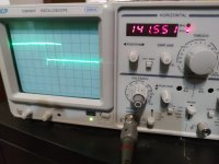
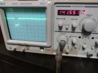
pin 9 and pin 10 seems to be the same freq.Why are you posting them?
Dave

daver2
10k Member
Or is it just because you are confusing the oscilloscope by not slowing down the timebase so that you can SEE a couple of cycles of the waveform on the screen each time you examine a new address pin?pin 9 and pin 10 seems to be the same freq.
Dave
Eudimorphodon
Veteran Member
FWIW, those scope traces are *really* nasty. Are the probes properly grounded? (And what are you using for triggering?)
There is good news here, though: Unless that frequency counter is completely off base it *very much* looks like the NOPs are running. These machines have a 2Mhz CPU, right? The 6502 manual says a NOP takes two cycles, which means it's going to running a million NOPs a second, and for every other NOP address line 0 is going to be high or low... so we'd expect pin 7 to oscillate at the roughly 500khz your scope is saying it's running at, right?
Another thing I'll call out: your scope traces might also be messy because I suspect the structure of that ROM I gave you might cause the program counter to roll over at an odd number, IE, you're going to have a "long cycle" when it hits the end and jumps back to the beginning again. If you wanted to get a cleaner view you could use two probes; clip one of them to A0 and make it the trigger, and then work through the higher address lines with the other probe; I think that should give you a nice set of increasing length traces. (A thing I say slightly hesitantly because I definitely don't have time right now to set that up on a breadboard.) Note also, I mentioned earlier: for a test like this if you want to save your 6509 from a little abuse you could measure the swings from the address lines on the EPROM instead; A0-A7 is pins 10->3, etc.
Anyway, again, my takeaway from this is at least sometimes this 6509 is capable of fetching instructions from the ROM sockets.
EDIT: So... a NOP is two cycles; once started it's going to be running 8187 of them, 2 cycles each, so we're looking at 16374 cycles of NOPs, and an absolute JMP takes 3 cycles, so... yeah? 16377 is an odd number, so every time this loops around you're going to have A0 stuck "long" for one cycle? That would cause the traces to jitter back and forth about 125 times a second if you didn't have your triggering set up correctly?
Last edited:
Eudimorphodon
Veteran Member
if you wanted to get a cleaner view you could use two probes; clip one of them to A0 and make it the trigger, and then work through the higher address lines with the other probe; I think that should give you a nice set of increasing length traces. (A thing I say slightly hesitantly because I definitely don't have time right now to set that up on a breadboard.)
... Actually, thinking about how I've messed with triggering on my video project, you might want the dedicated trigger to be the *longer* cycle. So... if this ROM is executing like how I think it should be a strategy here would actually be to use A12 as your dedicated trigger, because whether your scope interprets the trigger as high *or* low all the smaller transitions should be properly phased up with that. (IE, it would be like triggering on Hsync if you were trying to use a scope to look at a line of video data. If it interprets the trigger as going low you'll see the "start" of a cycle, IE, what's happening at E000, if it syncs up with the high transition you'll see activity from F000's perspective.)
Maybe I should make this clear: I am very much not a doctor, and if you've seen my Youtube videos you know I don't even bother trying to play one on TV.
Desperado
Veteran Member
- Joined
- Nov 25, 2017
- Messages
- 6,827
Yes 2 MHz! Great job for your nop!These machines have a 2Mhz CPU, right?
Tomorrow I'll check all the CPU addresses better! Thanks!!
Eudimorphodon
Veteran Member
These machines have a 2Mhz CPU, right? The 6502 manual says a NOP takes two cycles, which means it's going to running a million NOPs a second, and for every other NOP address line 0 is going to be high or low..
FWIW, if you do the math for the 566khz rate the frequency counter of the scope is reading for A0 that suggests the CPU is running at 2.264Mhz. The schematics say the B-series has an 18mhz master/pixel clock, it has 8 bit wide characters, and it’s pretty usual for machines like this to run the CPU at the character rate, which would be pixel clock/8.
2.264 * 8 = 18.112mhz
The NOPs are definitely running. It is worth verifying with proper triggering that all address lines from a0 to a12 are toggling at the correct frequency divisions, this success doesn’t rule out a stuck address line, but it is at least good news for the CPU. Like I suggested earlier, I would check the address lines at the ROM socket and only move to the CPU pins if you see one *not* toggling…
That would be a fantastic find, actually. If you broke a trace to the ROM sockets it would explain why it won’t run real firmware. Guessing it’s not going to be that easy, though.
Desperado
Veteran Member
- Joined
- Nov 25, 2017
- Messages
- 6,827
Ok thanks so much! Need i looking for a correct schematic with Rom address now!FWIW, if you do the math for the 566khz rate the frequency counter of the scope is reading for A0 that suggests the CPU is running at 2.264Mhz. The schematics say the B-series has an 18mhz master/pixel clock, it has 8 bit wide characters, and it’s pretty usual for machines like this to run the CPU at the character rate, which would be pixel clock/8.
2.264 * 8 = 18.112mhz
The NOPs are definitely running. It is worth verifying with proper triggering that all address lines from a0 to a12 are toggling at the correct frequency divisions, this success doesn’t rule out a stuck address line, but it is at least good news for the CPU. Like I suggested earlier, I would check the address lines at the ROM socket and only move to the CPU pins if you see one *not* toggling…
That would be a fantastic find, actually. If you broke a trace to the ROM sockets it would explain why it won’t run real firmware. Guessing it’s not going to be that easy, though.
daver2
10k Member
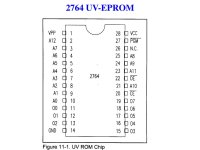
No, you just need to look for the datasheet for the 2764 EPROM you are using and look at the pinout to find the address lines.
Dave
Dave
Desperado
Veteran Member
- Joined
- Nov 25, 2017
- Messages
- 6,827
Thanks !No, you just need to look for the datasheet for the 2764 EPROM you are using and look at the pinout to find the address lines.
Dave
Attachments
daver2
10k Member
This is what I get (by calculation).
I surmise that you are not taking the measurements correctly (or there is something seriously wrong with either the EPROM, EPROM socket or the machine.
Dave
I surmise that you are not taking the measurements correctly (or there is something seriously wrong with either the EPROM, EPROM socket or the machine.
| Pin | kHz | Hz | |
10 | A0 | 566 | 566000 |
9 | A1 | 283 | 283000 |
8 | A2 | 141.5 | 141500 |
7 | A3 | 70.75 | 70750 |
6 | A4 | 35.375 | 35375 |
5 | A5 | 17.6875 | 17687.5 |
4 | A6 | 8.84375 | 8843.75 |
3 | A7 | 4.421875 | 4421.875 |
25 | A8 | 2.210938 | 2210.938 |
24 | A9 | 1.105469 | 1105.469 |
21 | A10 | 0.552734 | 552.7344 |
23 | A11 | 0.276367 | 276.3672 |
2 | A12 | 0.138184 | 138.1836 |
Dave
daver2
10k Member
On pin 2, I get 138 Hz (not kHz) and you are getting 283 kHz!
Dave
Dave
Eudimorphodon
Veteran Member
I surmise that you are not taking the measurements correctly (or there is something seriously wrong with either the EPROM, EPROM socket or the machine.
Yes. Those numbers genuinely make no sense unless there's just some kind of random thrashing going on instead of the CPU running NOPs. My old CRT scope doesn't *have* a frequency counter, so I'm not qualified to make any suggestions about how this one works, but this doesn't feel correct to me. So I vote we ignore it for now...
I raised some concerns about triggering before, @Desperado , did you do what I suggested with attaching a probe to A12 and using that as the trigger source for your scope? If you set the scope up that way and set the uSecs/div to somewhere in the ballpark of 2 you should, on A0, get a clean square wave about 1 divs wide; on A1, you'll get a square wave twice as wide, on A2 twice as wide again, etc... you should be able to keep working up through the pins in order with each pins until, as @daver2 's calculations indicate, you'll have to have the divs knob turned all the way down into the hundreds of hz range to see a whole wave.
To put this another way, if you worked a probe connected to an audio amplifier connected to these pins, which is a thing you might be able to emulate with your logic probe, *down* through the address lines you'd hear a set of ragged musical notes starting roughly around a third octave C# with A12, fourth octave C# on A11 (the black key above middle "C"), fifth octive on A10, etc, until the tone got too high for most people to hear around A5. (I could have heard it when I was a kid, but not anymore. A4 is dog territory, bats wouldn't *quite* be able to hear A2.) Any other behavior means your CPU is just screwed.
daver2
10k Member
Are you changing the oscilloscope timebase to ensure you get at least two of the signal pulses on the screen?
Think about it. How can the oscilloscope measure the frequency unless it has at least one complete waveform cycle to measure?
Is it possible that the oscilloscope is taking a frequency reading for (say) A5 and then you move on to A6 and the oscilloscope is still displaying the frequency for A5 because it CAN'T measure the frequency on A6? This would account for the series of duplicate frequencies on consecutive address pins wouldn't it?
As Eudi has already stated, synchronising the oscilloscope to something is important in this context. With a 'perfect' NOP generator the CPU is executing a continuous stream of NOP instructions, so each instruction takes EXACTLY the same amount of time. As a result, the address lines will be 'perfect' square waves (i.e. the oscilloscope will lock onto them regardless of when - in time - it starts the synchronisation).
With the ROM method, the CPU is mainly executing NOP instructions. However, to throw a spanner in the works, there is a JMP instruction at the end of the ROM back to the beginning. This means that you get 8,18x NOP instructions and 1 JMP instruction. The oscilloscope may be getting confused...
This is why we suggested triggering the oscilloscope on one edge of A12.
We are now back in territory where you need to understand HOW the oscilloscope works - and how to USE it. This means some study...
Dave
Desperado
Veteran Member
- Joined
- Nov 25, 2017
- Messages
- 6,827
But how can i do to trigger the scope on A12??This is why we suggested triggering the oscilloscope on one edge of A12.
CH2 on A12 and CH1 to check other pins?