| VCF West | Aug 01 - 02 2025, | CHM, Mountain View, CA |
| VCF Midwest | Sep 13 - 14 2025, | Schaumburg, IL |
| VCF Montreal | Jan 24 - 25, 2026, | RMC Saint Jean, Montreal, Canada |
| VCF SoCal | Feb 14 - 15, 2026, | Hotel Fera, Orange CA |
| VCF Southwest | May 29 - 31, 2026, | Westin Dallas Fort Worth Airport |
| VCF Southeast | June, 2026 | Atlanta, GA |
-
Please review our updated Terms and Rules here
You are using an out of date browser. It may not display this or other websites correctly.
You should upgrade or use an alternative browser.
You should upgrade or use an alternative browser.
CMB PET 3032 ( 2001N BOARD )
- Thread starter Desperado
- Start date
daver2
10k Member
The HIGH bank that is now mapped into the LOW bank (J).
Dave
Dave
Hugo Holden
Veteran Member
With the banks swapped the bank J becomes the lower bank. Previously when you were testing it, bank I was the lower bank.
As noted in the article I wrote, both the bank IC's can interfere with each other because their outputs are in parallel. It is unlikely all the IC's in one bank would be defective, but if you had one or two defective in each bank there can be a lot of data corruption. The trick is to narrow down the defective ones with tests, so that you don't remove good IC's by mistake.
If it were my board I would simply use the system I designed to locate the defective IC's. You could always make the hardware adapter I suggested on a proto board to get the computer running and take your time examining the RAM with POKES & PEEKS or with the M/L monitor or the ROM programs in the article which fill memory with checkerboard patterns and known bytes to assist the examination.
In the end, some people get "desperate" and simply replace the entire DRAM array, and this is not ideal. Probably most of your Toshiba brand ceramic body DRAMS are good and they look like nice chips. Most Japanese chips have a high reliability record.
daver2
10k Member
You would have to analyse the characters that are appearing - or try the piggyback trick on the J bank.it's possible that i have all 8 ic rams bad?
Dave
Hugo Holden
Veteran Member
The information we have so far does suggest at least one or more of the IC's are faulty, because we failed to identify any problems in the DRAM support circuitry and the values returned from the DRAM are corrupt and I think the buffer IC's have been checked, but it is a very long thread.
Depending on the types of faults in the DRAM IC's it could possibly help if the upper bank was disabled by tying that /CAS line high, it might remove some of the interfering effects between the two banks, but it would depend on the nature of the fault in the defective IC's.
Depending on the types of faults in the DRAM IC's it could possibly help if the upper bank was disabled by tying that /CAS line high, it might remove some of the interfering effects between the two banks, but it would depend on the nature of the fault in the defective IC's.
daver2
10k Member
Yes, we checked the data bus buffers to death!
We also checked all of the inputs to the address multiplexers to death.
That only leaves the address multiplexers and the DRAM devices themselves.
It is a shame we can't get my little test program working though...
We never did work out whether it was running or not though. @Desperado just stopped when he didn't get the correct display and didn't carry on to take the pin measurements that I asked for.
Dave
daver2
10k Member
Based on the last set of multiplexer output testing, and comparison with Hugo's results, we couldn't observe any faults. So, it is highly likely that replacing the multiplexers may not help...
Dave
Dave
Desperado
Veteran Member
- Joined
- Nov 25, 2017
- Messages
- 7,880
But i piggy backed every ic ram and i have always same faultBased on the last set of multiplexer output testing, and comparison with Hugo's results, we couldn't observe any faults. So, it is highly likely that replacing the multiplexers may not help...
Dave

daver2
10k Member
Have you actually analysed the sequence of character changes on the display or not?
If you are piggybacking one DRAM device at any one time (and there is more than one faulty device) the observed fault won't completely go away, but it will change.
You also have to remember that piggybacking only works for a sub-set of of fault modes. It is not a magic bullet.
Dave
If you are piggybacking one DRAM device at any one time (and there is more than one faulty device) the observed fault won't completely go away, but it will change.
You also have to remember that piggybacking only works for a sub-set of of fault modes. It is not a magic bullet.
Dave
Hugo Holden
Veteran Member
Desperado, you repair so many PETs that you really need to get used to analyzing/interpreting the PETTESTER results of memory checking. Or have other helpful tools.
The other way is to use my system, that way you interpret the bytes returned from defective memory. It is easy from the byte values to determine which bits are playing up.
In either case, if you don't do one of these things, you won't be able to narrow it down to the defective IC's in the cases where they are soldered into the pcb and especially if a few are faulty. That will leave you with no option but to replace them all, or replace one by one, until the fault clears, but Murphy's Law says that will be the last chip you un-solder !
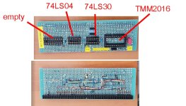
I would recommend if you get stuck on this one, put the PET aside for a while and build the adapter I suggested and program the ROM in the article (you know how to do this manually now). It will also help you with your soldering and construction skills. Try to do a tidy job on it. When I built the first one I simply did it on some proto-board with soldered link wires made from wire wrap wire. (see attached photo). Then you will have it for future PET repairs in your "Tool Kit"
If I could see the defective bytes returned from DRAM memory using this system, I probably could figure out which of the DRAM IC's are defective. And you could too by looking at the returned bytes and writing out the bit pattern.
In the case of the PETTESTER, Daver2 is the expert there on what the returned results mean.
If you got really stuck and for some reason couldn't make the board yourself, I could sell you a working and tested board (like the pcb shown in the article) for $60 plus post. But it would save you $ if you built it yourself.
The other way is to use my system, that way you interpret the bytes returned from defective memory. It is easy from the byte values to determine which bits are playing up.
In either case, if you don't do one of these things, you won't be able to narrow it down to the defective IC's in the cases where they are soldered into the pcb and especially if a few are faulty. That will leave you with no option but to replace them all, or replace one by one, until the fault clears, but Murphy's Law says that will be the last chip you un-solder !
I would recommend if you get stuck on this one, put the PET aside for a while and build the adapter I suggested and program the ROM in the article (you know how to do this manually now). It will also help you with your soldering and construction skills. Try to do a tidy job on it. When I built the first one I simply did it on some proto-board with soldered link wires made from wire wrap wire. (see attached photo). Then you will have it for future PET repairs in your "Tool Kit"
If I could see the defective bytes returned from DRAM memory using this system, I probably could figure out which of the DRAM IC's are defective. And you could too by looking at the returned bytes and writing out the bit pattern.
In the case of the PETTESTER, Daver2 is the expert there on what the returned results mean.
If you got really stuck and for some reason couldn't make the board yourself, I could sell you a working and tested board (like the pcb shown in the article) for $60 plus post. But it would save you $ if you built it yourself.
Attachments
Last edited:
Desperado
Veteran Member
- Joined
- Nov 25, 2017
- Messages
- 7,880
Thanks Hugo but I've already bought the Romulator and I think it's more than enough for these tests....this Pet is a special case unfortunately, usually only Dave's pettester eprom has always discovered the defective ramsDesperado, you repair so many PETs that you really need to get used to analyzing/interpreting the PETTESTER results of memory checking. Or have other helpful tools.
The other way is to use my system, that way you interpret the bytes returned from defective memory. It is easy from the byte values to determine which bits are playing up.
In either case, if you don't do one of these things, you won't be able to narrow it down to the defective IC's in the cases where they are soldered into the pcb and especially if a few are faulty. That will leave you with no option but to replace them all, or replace one by one, until the fault clears, but Murphy's Law says that will be the last chip you un-solder !
I would recommend if you get stuck on this one, put the PET aside for a while and build the adapter I suggested and program the ROM in the article (you know how to do this manually now). It will also help you with your soldering and construction skills. Try to do a tidy job on it. When I built the first one I simply did it on some proto-board with soldered link wires made from wire wrap wire. (see attached photo). Then you will have it for future PET repairs in your "Tool Kit"
If I could see the defective bytes returned from DRAM memory using this system, I probably could figure out which of the DRAM IC's are defective. And you could too by looking at the returned bytes and writing out the bit pattern.
In the case of the PETTESTER, Daver2 is the expert there on what the returned results mean.
If you got really stuck and for some reason couldn't make the board yourself, I could sell you a working and tested board (like the pcb shown in the article) for $60 plus post. But it would save you $ if you built it yourself.

Hugo Holden
Veteran Member
Thanks Hugo but I've already bought the Romulator and I think it's more than enough for these tests....this Pet is a special case unfortunately, usually only Dave's pettester eprom has always discovered the defective rams
It is the thought processes, analyzing the test results from diagnostic equipment, which "discovers" things like defective RAMs, or any other circuit defects. This applies whatever the test system and test equipment is that you choose to use.
The greatest tool in the laboratory, in fault finding, is always the thing between the ears.
I suspect though, that you would be better to use the system I suggested for one simple reason; You will find it easier to interpret the data returned from defective memory when it is presented to you in byte form. So I would advise that you build the adapter I suggested on some proto board and start to examine your DRAM memory. Otherwise just randomly replacing IC's is like flying blind.
Last edited:
Hugo Holden
Veteran Member
I said this in post #983:
Probably most of your Toshiba brand ceramic body DRAMS are good and they look like nice chips. Most Japanese chips have a high reliability record.
And this in post #996:
I would advise that you build the adapter I suggested on some proto board and start to examine your DRAM memory. Otherwise just randomly replacing IC's is like flying blind.
So I am really not surprised by your findings.
Interpreting PETTESTER results will help you too.
In addition, you checked all of the outputs from the Multiplexers, no obvious defect was found. It is still possible that there could be a defect in the timing of pulses there, but given the similarities of your recordings to those in a working PET it seems unlikely your multiplexers are responsible. Lets see what Daver2 says about it too.
daver2
10k Member
The results we have obtained from swapping the two banks of 16K over are completely inconsistent.
With the 'I' bank we get one good page and one completely bad page (the value returned is always $2E for this page). This would imply a multiplexer or an address line.
However, the 'J' bank exhibits a completely different fault scenario.
If it was a multiplexer, or an address/data buffer, then I would expect that fault to be applicable to both banks of RAM - as it is external to the RAM. But it isn't.
I must admit that the fault does imply that the DRAM is at fault...
Now, you did check the power supply rails for both high and low frequency noise didn't you @Desperado? If we have noise on the power rails (especially the +12V and/or -5V) then we are chasing ghosts!
The other possibility is a timing fault in the signals driving the multiplexers. We haven't checked these yet, and they should be a simple check with the oscilloscope.
I am also not happy why my little test program didn't seem to work. Did you take the signal measurements I asked for or not?
Dave
Last edited: