• Please review our updated Terms and Rules here

CMB PET 3032 ( 2001N BOARD )

We are not continuing with the tests until you become more proficient with your oscilloscope. We are both wasting our time (in my opinion).

I (personally) would not replace the multiplexers until I knew they were faulty. This is, after all, what the oscilloscope, your brain and the test software should indicate. But, if you can't configure your oscilloscope correctly (or understand that you have misconfigured it) then it is no more use than a doorstop I am afraid.

I do belive (in one of the many, many posts) that I have recommended the order in which you replace the multiplexers - as (based upon the PETTESTER results) some multiplexers are more likely at fault than the others.

In any case, I would get the PETTESTER running (with the g, b and . display) and replace the multiplexers one at a time and look for changes in the PETTESTER display after each IC replacement.

Dave
ok, thanks!
 
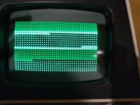
I am desperate, i changed all LS153 with new ics but the situation is worst!!
 

Attachments

  • 1685209911719..jpg
    1685209911719..jpg
    1.6 MB · Views: 6
Time to white flag and time to send this bad board to my friend, prof Antonio Caradonna.... He maybe can repair this dirty board 🤬
 
That makes more sense now to me that either all of the DRAMs in the lower bank are completely broken, or there is a control signal timing fault.

Either that, or the 153 devices all worked correctly before and you have introduced a new fault when you replaced them.

I was trying to look at the control signals with my testing, but your oscilloscope capabilities are clearly not up to that yet.

I am not repairing any more computers with you until you improve your knowledge of basic digital logic (how some of the ICs in a PET work) and how to effectively use your oscilloscope.

It is taking too much of my time to keep explaining the same diagnostic techniques over and over again. You have to learn for yourself and then apply this knowledge to future repairs without me having to hold your hand every time.

There has to be books on this subject in Italian for you to learn from. This will involve you putting in some time...

Dave
 
If you are going to ask someone else to repair this PET, can I ask that you post what the fault(s) actually turn out to be.

We need to get something out of this mega thread for the future...

This is a fault that I have never seen before, so knowing what it turns out to be will extend my knowledge!

Dave
 
If you are going to ask someone else to repair this PET, can I ask that you post what the fault(s) actually turn out to be.

We need to get something out of this mega thread for the future...

Dave
Yes sure!! I have to decide whether to have it repaired (for a fee) by a friend or whether to sell it like this in this state .... I'm desperate!
 
Desperado: You did have the option to build the adapter board I suggested to examine your memory. Also, using it, if your computer booted normally with it and ran BASIC in 2k mode and ran small programs, you could have been confident that there wasn't another problem hiding on the board, other than DRAM memory & its support circuitry that you needed to look for first.

Then you could have examined the DRAM memory bytes and easily worked out which of your DRAM IC's were faulty according to the methods in the detailed article and the diagram there. But you chose not to go down that road.

However, as Daver2 says, your skills do need improving, the adapter would actually be a good small construction project for you, to make it, to also improve those skills. Many people develop their electronics skills with various construction projects. It especially helps with soldering skills. You are not completely without skills though, so you can be congratulated, especially for your effort, but overall the skills are not yet at a level for generally successful vintage computer repairs and it requires too much hand holding by Daver2, who, as the old saying goes, has the patience of Job.

I also pointed out that if you made the adapter, you could use it on future PET repairs and keep in your tool kit. But you said this PET was a special case. But it isn't really. Many PET's with soldered in DRAM's have the issue of trying to figure out if 1) it is a DRAM issue or something else related to their operation and 2) which of the specific DRAMs IC's are defective. Your board is far from a special case in this respect, though as Daver2 pointed out, he has not seen this particular fault before and we all want to find out what fault/s are causing it.

You also fell for the trap of replacing IC's on hunches. This is a poor proposition, because there is a risk of introducing new faults such as pcb damage and shorts. The IC's you fit might be faulty and/or not ideal. (For example you said you fitted LS153, but the originals are 74153, probably ok but not 100% certain in every case). Now you have seen that things have "changed" which could mean another fault is added and it likely means the original 74153's were ok. This is how many people get themselves into a real pickle with repairs. An IC should only be removed where there is good evidence, based on measurements, to indicate it is actually defective.

I once repaired a pcb for a person who had a go at it. The board contained about 65 TTL IC's, they replaced about 35 IC's and got nowhere on hunches. By the time I fixed it, the original defective IC was not one they replaced. They introduced pcb damage and a "new" IC they had installed was also defective. The board of course, in the end, though I got it functionally working, was ruined and it also had no historical value either because of all the pcb patches and non original IC's.
 
I'm going to tackle a similar 3032 system as my next PET repair project and have tried to follow this thread but it ran faster than what I could read. :)

What would be a short summary of the symptoms and the possible causes contemplated?
 
Half of the posts are mine - and I can't follow it either!

A 3032 is a 'bog standard' PET with the added complication of Dynamic RAM - and we never did get to the bottom of that either...

I would save a day of your life and start again from what you already know.

However, there are a couple of very useful diagnostic 'tricks' I devised here to test out the DRAM data buffers by disabling the DRAM devices themselves with a simple wire link. I can explain this neat trick separately in your thread.

Dave
 
Good Morning guys, tanks so much for your great support! since I paid too much for this computer, it would cost me too much to have it repaired. I therefore decided to sell it in this state, someone will definitely buy and fix it. I'm very sorry I didn't find the fault.
 
Half of the posts are mine - and I can't follow it either!

A 3032 is a 'bog standard' PET with the added complication of Dynamic RAM - and we never did get to the bottom of that either...

I would save a day of your life and start again from what you already know.

However, there are a couple of very useful diagnostic 'tricks' I devised here to test out the DRAM data buffers by disabling the DRAM devices themselves with a simple wire link. I can explain this neat trick separately in your thread.

Dave
100%, keen to hear about the diag methods you developed!
.
I might get side tracked first to build a signal gen for the 9" and 12" monitors. I pulled one of my 8032s for donor IO chips and it see it now suffers from vertical collapse. Another 8032 (possibly 2) I have has a very faint display. I've been avoiding fixing them but can't ignore it any more. Want to make a small circuit that can generate both the 9" and 12" signals so I can easily work on the monitors. Will start another thread for that soon.
 
Sounds interesting...

My 'trick' is to connect G7 pin 1 (74LS10) to 0V. This will prevent the DRAM /CAS signals from being generated so the DRAM never responds to a read or write request.

With PETTESTER running - and 'stuck' on the initial page 0 and 1 RAM test, you can then connect the output data bits from the DRAM high and low and the pattern should be displayed on the PETTESTER screen (in PETSCII).

Using this technique, you can test each data bit of the DRAM buffers for HIGH and LOW without desoldering them.

Simples...

You remove the temporary link afterwards.

Dave
 
FyI I seem to have some time on my hands so would look at it for a very small, tending to zero, fee.... You would need to pay postage both ways to the UK so probably prohibitive. I love a challenge.
 
Back
Top