• Please review our updated Terms and Rules here

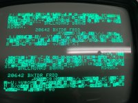
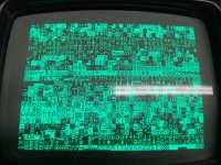
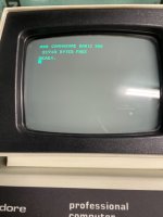
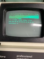
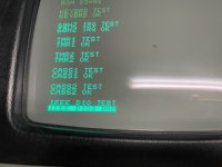
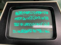
Commodore 3016 scrambled screen

It could be a bad PCB trace. It could also be a bad IC (not completely dead but marginal).

Have you tried my PETTESTER first to make sure your ROM checksums are correct AND stable? Assuming you get that far and my PETTESTER doesn't find fault with the video RAM logic...

Dave
 
At this moment i only get the first screen as in post #300. Pettester is not working when i have this problem. Last week when it was working it ran for hours with no problems.
 
Can you post a photograph of the screen please.

Can you also check CPU pin 7 (SYNC) for activity. If no activity, then PETTESTER is not actually running, and the CPU has crashed.

If there is activity, it indicates that access to the video RAM is not correct, and we can inspect the circuit with the oscilloscope.

Dave
 
But that's not my PETTESTER, so I can't specify any points to monitor with your oscilloscope so that we can hunt the problem down...

With the PETTESTER I know what it should be doing, and (therefore) what the waveforms should look like.

Dave
 
Ok. That looks address line related.

You didn't say whether CPU pin 7 has a signal on it or not though.

I am going out for my evening walk...

Dave
 
Ok, you have a cause and effect then.

IC sockets, rusty IC pins, faulty PCB tracks (may be short circuit as well as open circuit.

Dave
 
Pettester has no error's
I was also testing IEEE488. Somewhere on this forum you mentioned the hardware book

PET and the IEEE 488 Bus (GPIB)​

I tried the listing on page 184 Diagnostic Test.

In this test the output says GBPIB databits are bad

THE BAD GPIB DATA BITS ARE:
BIT 7
BIT 6
BIT 5
BIT 4


etc.

How relaiable is this listing?
 
You need to manually check the IEEE488 buffers chips. I am busy at the moment, but I will post information later.

Dave
 
In the book (and the program) are the PEEK and POKE statements for reading from (and writing to) the IEEE488 port.

First, POKE a value of 0 to the IEEE488 data port and PEEK the value back. Then measure the voltages on all of the pins of the IEEE488 buffers.

Second, POKE a value of 255 to the IEEE488 data port and PEEK the value back. Repeat the voltage measurements.

Post the results back and from that we should be able to work out what component is faulty.

When you say "etc." above, do you mean that all of the data bits appear to be faulty?

Dave
 
I assume the control bits are OK though?

The IEEE488 buffers are usually MC3446 parts.

There should be three (3) devices. Two of these handle the data bus and the third the control signals.

On the schematic I am looking at, A7 and A8 handle the data bus and A9 the control signals.

It is possible that the previous owner plugged something in incorrectly and damaged the data bus buffers. These things also have a high failure rate anyhow.

Dave
 
Back
Top