Desperado
Veteran Member
- Joined
- Nov 25, 2017
- Messages
- 7,880
Good evening everyone and happy holidays to the entire forum!
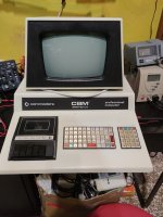
I kindly ask your opinion on this Pet 2001-N, a gentleman asked me if I can repair it for him...
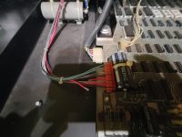
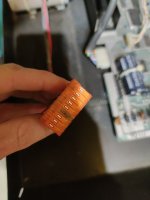
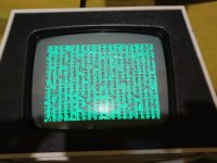
He told me that when I turned it on it showed the usual screen with random characters and symbols. As soon as I brought it home, I didn't turn it on but when I opened it I immediately saw that there is a cable (number 4 on the connector) that is cut. Also on the connector, on pin 4 you can see a burn mark. What could have happened?
Thanks everyone
I kindly ask your opinion on this Pet 2001-N, a gentleman asked me if I can repair it for him...
He told me that when I turned it on it showed the usual screen with random characters and symbols. As soon as I brought it home, I didn't turn it on but when I opened it I immediately saw that there is a cable (number 4 on the connector) that is cut. Also on the connector, on pin 4 you can see a burn mark. What could have happened?
Thanks everyone