Desperado: Some things abut reading and wrint to SRAM memory chips:
One good piece of news is that the process id simple in that it does not require all the support IC's and extra circuitry that DRAM requires.
Normally with SRAM its data lines are connected to bi-directional buffers to apply the data to the chip when it is being written and extract the data from the chip when it is being read.
Chips such as the 74LS244 are bidirectional Tr-istate buffers are used for the task, in the PET, E7 and E8 as you know.
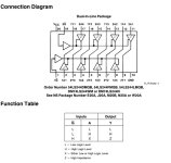
Each of the 4 buffers in the IC package has a control line to select a group of 4 buffers on pin 1 and pin 19, these control lines are active low. This is why there is a small circle printed on the the diagram on the schematic where the input wires connect to pin 1 and pin 19. You can see the way they have wired with those pins so that the data pathway is selected to write data into the video RAM or read data out of it to display on the video.
The bidirectional nature works works because when the buffers are not selected (the control line is logic High), they effectively vanish from the circuit, because their output goes to a very high impedance state and those buffers input are effectively ignored too because they then have no effect on anything. This is why they are called Tristate, because when they are selected they will pass a high or a low through them, but they have the 3rd state too.
Some Tristate buffers are inverting, some not. If you are considering checking the buffers (or any logic IC for that matter, if you are not very familiar with it already) the first thing to do is to print out the internal diagram, attached.And notice that there is a separate buffer for each direction of the signal. Which means that it is possible for just a single read bit or a single write bit to fail. Or more than one bit, or a group of 4 bits of read & white together and also fail on a condition of three states of a group of 4, either stuck tristated, and ignoring its inputs, and possibly even with stuck output pins, which would interfere with both the reads and writes. Because of the possibilities it requires a lot of examination with the scope to determine if a buffer IC is faulty or not for both reads and writes and its tristate function. Unless you unsolder it and have a suitable tester, but the goal is not to unsolder good IC's.
In the case that the data emerging from the SRAM is incorrect on a read, and doesn't match what you think was put in there on a write, it raises the question, just in the instance that the data source was normal in the first place, whether or not the data in the SRAM is actually normal, and the read process is corrupted, or if it was the write process that was corrupted by a buffer fault, and the read process is normal, or possibly both processes are corrupted. Or the SRAM itself is defective. Don't forget that the SRAM Devices themselves contain circuitry that controls their reads and writes and defects in there can resemble the effects of faulty external buffer chips.
Then there is the question of the initial data source being correct, or not and the logic signals controlling the buffers. That gives 6 possibilities at least, where one or more of them could be simultaneously true.
As you know, the read pathway can be readily checked by removing the SRAM and using resistors to apply a 8 bit code to their data pins and looking at the video screen. But that doesn't discount failures in the write side, or that any of the packages of ROM data, write gates in the data buffer IC's or SRAM IC's memory cells or internal logic still have an issue. It just confirms that the read pathway from the SRAM socket and likely the control signals are working, via the read buffers in the 74LS244 are ok and the integrity of the video circuitry is good.
The bottom line is, in a Tristated system of memory, there are many possible fault combinations, that is why I use the approach of eliminating initial variables first, fit the known good SRAM, known good ROMs before any scope fault finding of the buffers or you can end up chasing your tail for a long time.
While the 74LS244 buffer IC's in PETs can fail at times as they can elsewhere, they have to be 100 x more hardy than the original 2114 SRAM chips which have been found to be failed in practically every PET repair. Any signs suggesting read/write issues are far more likely to be inside the SRAM IC that in the 244 buffers. So to start on the repair process, especially if they are already socketed is to fit a known good pair of 2114 chips. In addition it is not uncommon to have defective ROMs and corrupted ROM data. As I mentioned, before this fixed PET escapes your clutches, make a service kit of known good ROM, DRAM and SRAM to help you fix the next one.
")