• Please review our updated Terms and Rules here

Commodore Pet 3032 no power

Articat

Experienced Member
Joined
Nov 23, 2022
Messages
60
Location
Sweden
Many thanks Dave! That's what I call a good description. I will follow your instructions and report back in the thread in a few days.

I've looked a bit on the internet for those TO-3 voltage regulators, but they seem to be hard to come by. So it should probably be possible to put in regular 7505 regulators? But it might not be so pretty.
 

daver2

10k Member
Joined
Jun 19, 2012
Messages
12,446
Location
UK - Worcester
Let's see whether they work or not first shall we, and then worry about a replacement if they are faulty.

Dave
 

Hugo Holden

Veteran Member
Joined
Dec 23, 2015
Messages
3,997
Location
Australia
I've looked a bit on the internet for those TO-3 voltage regulators, but they seem to be hard to come by. So it should probably be possible to put in regular 7505 regulators? But it might not be so pretty.

Part of it is most TO-3 package regulators don't go under the 7805 name very often. You will find more if you search under UA7805 on ebay. Avoid late manufacture ones from the far east with the large blue areas of glass insulation where the pins exit the body, there are a lot of poor clones +/- fakes for these parts, much like the proverbial 2N3055. Get early date code ones that look original where possible.

The "classic" 5V TO-3 voltage regulator from the 1970's era was the LM309k. These are easy to get and still were sold even now I think by the major suppliers, but are called "LM309k-Steel".

Yep: still have em in stock at Newark, but not cheap:


a little cheaper at digikey:


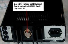
I have a large collection of the original LM309k's, these were made by National Semiconductors, they have a gold plated base, they are true works of art and the internal design & the protective systems were inspirational. Last time I looked Surplus Sales of Nebraska has some of these gold plated originals left.

But, there are some very good replacements that are mil spec types with an entirely different number system M38510/10706BYA. If I were fitting new regulators to my PET, I would use these, really really good quality parts, this seller is very good too:


A few sellers charge nutty prices for these mil spec parts, So if you need some get those ones from Huskerfan as it is a sensible price at $14.99.

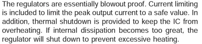
(Here is a trap never to fall into; Of late some designs have appeared using electronic switching modules to replace TO-3 voltage regulators, or the 7805, in the interests of less heat dissipation. But, they are not as good in every other respect including output noise but worse, don't have the sophisticated thermal and and current overload/short circuit protection features of the original 7805 and not only that, they have failure modes where they can can over-voltage their outputs and damage IC's they supply. I don't go near these with a barge pole. The analog regulators practically never fail this way, with time and age the worst they do is have an output voltage that is a little low. It is better to have the heat dissipation and the safety intrinsic to the analog regulator that National Semiconductors created)

I have attached a photo of National's original part on a home made power supply. I have also attached a remark from National's data sheet. Perhaps tempting fate saying they are "blowout proof", but on the whole I would have to agree they are.

Another detail, there were some beefed up versions made that were good to 5A load, I think they were the uA78H05 by Fairchild...yes here is the .pdf:


Attachments

  • LM309k.jpg
    LM309k.jpg
    101.1 KB · Views: 3
  • LM309K2.jpg
    LM309K2.jpg
    76 KB · Views: 3
Last edited:

Articat

Experienced Member
Joined
Nov 23, 2022
Messages
60
Location
Sweden
These TO3 voltage regulators has 2 pins not 3.
And how it is possible to see the polarity on these guys?
 
Last edited:

daver2

10k Member
Joined
Jun 19, 2012
Messages
12,446
Location
UK - Worcester
The case is the third pin... Therefore two physical pins and the case makes three.

Not sure what you mean by polarity. If you look on the Internet for the part number and locate the data sheet it should tell you everything you need to know. These parts, from their schematic position, should be positive regulators giving a fixed output of +5V. You need at least +7.5V on the input to give +5V on the output.

Dave
 

Articat

Experienced Member
Joined
Nov 23, 2022
Messages
60
Location
Sweden
@Dave
Sorry my english is not top notch. I meant of course if they were polarity sensitive. i.e. if it matters which way you turn them. The reason I ask is that there is no marking on them whatsoever. There is usually a plus or minus, alternatively a dot or arrow etc.

Incidentally, Commodore has been so kind as to have riveted the 7805 regulators in the motherboard so these have to be drilled out.

I'll take a look at the 7805 schematic and see if I get any wiser.

@Hugo Holden
Thanks alot for your post man!
You gave me some really good advice. I have never worked with these voltage regulators. These links will come in handy.
 

daver2

10k Member
Joined
Jun 19, 2012
Messages
12,446
Location
UK - Worcester
No problem at all. Your English is much better than my Swedish!

Yes, all semiconductors (and voltage regulators are semiconductors) are generally polarised.

The ground is the reference point. The input has to be positive relative to the ground. The output will also be positive relative to the ground (+5V in fact).

As to the pinouts, there are no markings whatsoever on the TO3 part. Even if you unrevited it and desoldered it from the printed circuit board, there will still be no observed markings whatsoever.

The data sheet for the part details the pinout. This is the only way you know for sure which pin is which.

If you look at the two pins of the TO3 package you should notice they are slightly off the centre line of the package. This permits you to correctly align the physical part with the datasheet pinout.

When I get my PC booted up (I am on my phone at the moment) I will find the data sheet for you so you can see what I am talking about.

Dave
 

Hugo Holden

Veteran Member
Joined
Dec 23, 2015
Messages
3,997
Location
Australia
The data sheet link I posted on the uA78H05 on post #23 shows a cut away version of the TO-3 case positive regulator viewed from the top.

Most data sheets show the view from the bottom of the device (attached). With the two mounting holes aligned on a vertical line, and the two pins sitting on a horizontal line, above another horizontal line that would divided the space between the two mounting holes in half, the Input pin is always on the left for positive regulators in the TO-3 case. BUT not if it is a negative voltage regulator where the case is the input.

Of interest, this Input pin position is the pin that is normally the Base connection of a typical TO-3 case power transistor.

( just a side note: It is a the same for the flat pack to-220 case regulators like the 7805, and the negative regulator version 7905, be very careful. On the 7805 the ground is the central pin and the metal tab too, but not for the 7905 where is is the input. So the advice here is, if you come across a negative voltage regulator, don't assume that you know the pin connections and double check the data sheet)

Most likely your regulators are in a shut down mode, so you might not have to drill out the rivets or replace them. More testing might help. If the regulator is in a shut down mode. The two regulators supply different 5V rails, and it would be unlikely to have a short on both. In any case when they go into shut down mode, even though the current is limited they still warm up because they drop the full applied voltage. Sometimes if the capacitors immediately on their inputs fail, they can go into HF oscillation, confounding meter readings.
 

Attachments

  • regbase.jpg
    regbase.jpg
    11.3 KB · Views: 5
Last edited:

Hugo Holden

Veteran Member
Joined
Dec 23, 2015
Messages
3,997
Location
Australia
.......further to the issues with regulators like this. They can be damaged if the output gets forced significantly higher than the input voltage, which is why you often, but not always, see a diode from their output to their input.
 

Articat

Experienced Member
Joined
Nov 23, 2022
Messages
60
Location
Sweden
@Hugo Holden
Thanks for the information. It should be possible to test the regulator in the circuit with the legs unsoldered. Then I can do the test Dave talked about.
As I said, I don't know much about these regulators. Are they more durable than standard 7805 regulators? I have only changed them (3 leg)a few times in old Atari 2600 brand videogame console
The regulators in the Vic 20/64 have never bothered me.

Is it possible to measure these in regulators in diode mode and see if they leak current in the reverse direction? In this way, you can sometimes find broken transistors.

Thanks for the picture Hugo Holden.
Give me a few days to figure this out and I'll report back in the thread.
 

Hugo Holden

Veteran Member
Joined
Dec 23, 2015
Messages
3,997
Location
Australia
Is it possible to measure these in regulators in diode mode and see if they leak current in the reverse direction? In this way, you can sometimes find broken transistors.

In short, no.

An analog voltage regulator is a moderately complex circuit. Not a single two or three terminal device like a diode or a transistor where you can examine a PN junction with a meter.

The diode mode tests on a meter, as they could be applied to a diode or a transistor, have no meaning at all applied to a complex device like a three terminal regulator.

You cannot use the meter to test the voltage regulator, aside from some gross abnormality like an input or output short (highly unlikely too).

The better way to check the regulator is in a powered circuit with a volt meter, not with a meter on Ohms range or diode test mode, in an un-powered circuit.
 

Articat

Experienced Member
Joined
Nov 23, 2022
Messages
60
Location
Sweden
@Hugo Holden
Ok, then the smartest way should be to simply turn the motherboard over and measure the input and output voltage directly on the voltage regulator. Without having to remove it. Because if there is power in and it does not give 5v out, it must be broken?
 

Hugo Holden

Veteran Member
Joined
Dec 23, 2015
Messages
3,997
Location
Australia
@Hugo Holden
Ok, then the smartest way should be to simply turn the motherboard over and measure the input and output voltage directly on the voltage regulator. Without having to remove it. Because if there is power in and it does not give 5v out, it must be broken?

No, not necessarily broken.

If you read up on these regulators from their data sheets, you would learn that they incorporate protective systems. If their output is overloaded, they will shut down. It does not mean that the regulator is "broken". So you need to determine if they are overloaded or not. Can you think of a way to do that ?
 

daver2

10k Member
Joined
Jun 19, 2012
Messages
12,446
Location
UK - Worcester
As I have have stated back in post #16 (and Hugo has also stated) the regulator may not be dead just because the output voltage is very low. It might have gone into shutdown mode because of either a high temperature or a high current flow. Once the voltage regulator has shutdown, you need to power it OFF to reset it.

For this reason (as a minimum) you need to disconnect the OUTPUT pin of the voltage regulators from feeding the PET circuitry.

Dave
 

Articat

Experienced Member
Joined
Nov 23, 2022
Messages
60
Location
Sweden
OK, I don't know if I did it right now. But I have freed the legs and put a resistor on the output leg then connected this to ground on the motherboard. I have then connected positive 9V on the input leg and negative on the output leg. I don't get any 5V this way. When I measure with a multimeter
 

SiriusHardware

Veteran Member
Joined
Feb 15, 2014
Messages
781
Location
UK
That doesn't sound quite right Articat - Your battery +V should go to the input terminal and your battery -V should go to the regulator GND terminal. You should measure the output voltage between the regulator output terminal and regulator GND.
 

daver2

10k Member
Joined
Jun 19, 2012
Messages
12,446
Location
UK - Worcester
>>> I have then connected positive 9V on the input leg and negative on the output leg.

Perhaps it is a translation issue, but according to the text in post #35 that is not what is stated.

What voltage are you measuring on the regulator output?

Is it possible that the regulator output pin is still connected to the PET circuitry somehow?

Dave
 

Articat

Experienced Member
Joined
Nov 23, 2022
Messages
60
Location
Sweden
Red is connected to input
Black is connected to output

There is no contenuity betwen the leg and the solderpad.

Readings are -350mv
 

Attachments

  • 20221201_191852.jpg
    20221201_191852.jpg
    1.4 MB · Views: 3

Hugo Holden

Veteran Member
Joined
Dec 23, 2015
Messages
3,997
Location
Australia
Assuming you connected it up correctly with the +9V source to the input pin, the negative of that source to the regulator's case (ground) and there is nothing coming out the regulator's output pin with respect to ground, that does suggest the regulator is faulty.

But before doing anything else, I would stop there. Buy a replacement regulator and test that with your experimental setup and prove that this regulator is working, to make sure you are not doing something wrong. It pays testing these regulators to have a capacitor as recommended by the manufacturer on their input and output. It is more important than an output load resistor. If there is HF oscillation it can confuse meter readings and you might miss that without a scope.

One word of caution. Under usual circumstances with the computer board powered by its transformer, rectifier, capacitor filter system, and a normal regulator, this ensures that the board's IC's never receive an over-voltage or reverse polarity accident. If you are applying any other kind of power source to the board, be extremely careful, as the is a higher risk of an accident that could badly damage a lot of IC's.

It is hard to tell from your photo what you have done.

The experimental setup needs to be what I have shown in the modified photo attached. You also have to check first that the pins of the regulator have definitely been isolated from the pcb pads. Also it is likely difficult to connect/solder to the Rivet to acquire the ground(case connection, so I would suggest soldering to the earth track ground nearby as shown on the photo.
 

Attachments

  • regtest.jpg
    regtest.jpg
    115.4 KB · Views: 8
Last edited:
Top