genobombino
Experienced Member
- Joined
- Dec 15, 2022
- Messages
- 53
I really need help with this.
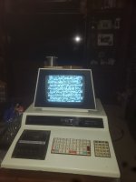
I have an original 2001-8 commodore pet with 6540 rom and 6550 ram chips. I bought it off of ebay for a ridiculous price with the description reading (screen powers on and functions fine). Yet, since Ive plugged it in, all i have a problem with IS the screen.
So here's the problem
the screen will randomly flicker, jump, distort, and whatever else you wanna call it. I had the commodore prompt actually working after moving around some chips and reseating the important ones, only to have the screen flicker throw it back into a garbled screen. Ive tried reslodering the monitor board, reseating the boot, replaced some capicitors, replaced the on board diodes, deoxit'd the whole board, even reseating the plunger, and have had no luck.
Im at a complete loss, any help would be appreciated immensely.