daver2
10k Member
Nope...
A resistor is a passive device. This is being actively driven...
Each IC TTL input pin has a very weak pull-up resistor inside. The recommendation is to always have an external pull-up resistor on unused inputs (as is the purpose of R39) but even with it not there, you shouldn't see what you are seeing.
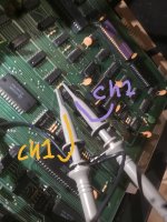
It is either 'conductive contamination' or a faulty input pin on either C5 or D5 connected to R39.
Something is 'driving' this network low.
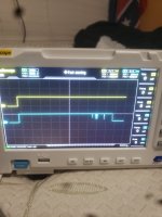
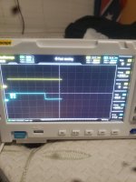
One option is to use your oscilloscope and accurately measure the LOW voltage on each pin of C5 and D5 connected to R39 looking for the LOWEST voltage. This may indicate the faulty pin... But your oscilloscope may also not be up to the task.
Dave
A resistor is a passive device. This is being actively driven...
Each IC TTL input pin has a very weak pull-up resistor inside. The recommendation is to always have an external pull-up resistor on unused inputs (as is the purpose of R39) but even with it not there, you shouldn't see what you are seeing.
It is either 'conductive contamination' or a faulty input pin on either C5 or D5 connected to R39.
Something is 'driving' this network low.
One option is to use your oscilloscope and accurately measure the LOW voltage on each pin of C5 and D5 connected to R39 looking for the LOWEST voltage. This may indicate the faulty pin... But your oscilloscope may also not be up to the task.
Dave