• Please review our updated Terms and Rules here

Commodore PET restoration help needed

Which, in my case would probably only be after i tried to use an adapter to burn a 2532 on 2732 settings but failed.

Note that an adapter to burn a 2532 on the 2732 setting requires the adapter with an isolation diode to protect one of the pins from the 25V. Make sure you use the correct adapter schematic. I failed to quickly find the schematic but others here will have it.
 
Alright, my first attempt of burning a 2716 chip failed. I tried to Burn daver2's PETTESTER. I will attach pictures if i figure out how. Im not entirely sure what i did wrong, an im not entirely sure how to correct it. But i do have my UV lamp to test now so theres that.

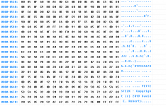
Anyways, here are the pictures: What the code looks like (the end bit with the copyright note):correct.PNG

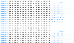
and here what my chip reads after burning it (note the copyright is still intact):wrong.PNG

I have a second 2716 if my UV lamp isnt up to the task.

SkyCaptain
 
You didn't have the right place in memory. If the Pet code in a HEX file? It might have an offset that you need to account for. The code you got looks like a random memory dump from someplace.
I don't know what code you are using to program the part but usually they have some method to either offset the read of the file into the buffer or the same to offset the location to blow the EPROM from.
I didn't expect such a complete list of wires. Did you measure from the socket or as I requested from the pin of the device?
The numbers look fine.
Dwight
 
For the connection testing of the 6520 i tested both the pins to the part, and then also the pin of the socket on the back side of the board. So i think i did both. I still havent traced down the two or three where i couldnt make any connection from the pin to the part. So i really still have to finish that before i can really say nothing is wrong. And im sorry for the info dump, I just thought sharing the raw data would be more helpful than drawing my own conclusions from it.

For the EPROM, I open the software, and select my chip type from the long list. Its SGS-Thomson M2716. The programmer gives me a picture of how to place it into the socket.
The code that daver2 has provided is both in a bin and a hex file. When i try to load the hex file, programmer software doesnt change. So i load the bin file and it fills the the "FLASH" window with what i presume is the program. So i first read the chip to make sure its empty, it shows only "FF" in every location. Then i load the bin file again, and start the process. It finished after a few seconds with that result. I did not see an error. After the burning was done, i read the chip and saw that the information has changed.

Would that offset be called offset in the programmer? Also there is some sort of buffer function/setting that i have not touched at all. When you say "looks like a random memory dump", could it be that i have to like clear the buffer in any event before writing?

Edit: So i think i may have found that "offset" thing. When i load either file, the software asks for "From File start address(Hex) "00000"" and "To Buffer Start Address(Hex) "00000". Here i could create an "offset" i guess?

SkyCaptain
 
Last edited:
Yeah ok, i think i have found the issue although i dont really understand enough to solve it.
in the archives of this Forum, i found a conversation which im going to copy paste a few bits out of.

"
Daver2: The HEX file was used to produce the BIN file itself. Don't forget that your EPROM programmer may require an offset to be added or subtracted from the base address of $E000 within the HEX file.

Dave_m: Yes, that was it. On the Data I/O, the command that worked with your hex file was:

COPY PORT E000 0800 RAM 0000

This transferred a file with starting address $E000 with a block size of $0800 (2K decimal) to RAM at starting address $0000. Normally I'd use the default of 0000 with the COPY command.

"

but yeah, i do not fully understand what this means. Sorry guys.


SkyCaptain
 
The hex file has the address encoded in it. The binary doesn't. If you load the hex file, you either have to tell it that the data starting at E000 has to be put in location 0000 or when programming the EPROM you tell it to start at E000.
I'm not sure what the problem with the binary is. There is no offset address in the binary file. It has been a long time since I used a Data I/O so I'm not familiar with the commands for it. I'm currently using a Needham programmer. I do have a older Data I/O in storage someplace.
The EPROM it self is like the binary file. It has no idea where in the memory map it will go. the E000 to E7FF part is decoded on the board and use for the select pin to the EPROM.
On the Pet, the ROMs have some of the address decoded by the combinations of high and low select pins. This makes it a pain for us hobbyist that wish to use standard EPROMs in place of the ROMs. It requires extra circuits put on adapter boards. An alternate is to replace several ROMs with a single large size EPROM.
Luckily for the Edit ROM, a 2716 can be plugged right in. This is the reason it was the chosen location for the debug code. It would have been more robust to be at the address space with the reset vector but that would have required an adapter to use a standard EPROM.
Dwight
 
Alright, thank you dwight, with your explanation about having to tell the Hex file where to start, i was able to load it properly and the "preview" of the code looks as far as I can tell, the same way as it would if I loaded the Bin file.

Maybe the issue is with basic settings? I have 4 to select which i havent touched
VPP voltage set to 25V, VDD Write set to 5V, VCC Verify set to 5V and finally Pulse Delay 1000us.

My UV lamp is taking its sweet time to erase the chip but it is working.. i think.

Also if i understand this correct, even if i have the 2532 chips, i will in any event need a adapter to replace the original ROMs in case they are shot?

Edit:


OK no wow, i dont know what went wrong with the first Chip, i did it again with the second one that i have and it ran and passed verification. And taking out, restarting the program and reading the chip again does look like the Copyright is now fully intact, all 4 lines . So now i will try and plug this baby into the Edit ROM slot.

SkyCaptain

SkyCaptain
 
Last edited:
Also if i understand this correct, even if i have the 2532 chips, i will in any event need a adapter to replace the original ROMs in case they are shot?
SkyCaptain, The 2532 is pin for pin replacement for your 4K ROMs and do not need an adapter in the PET. You will need a special adapter to program the 2532 on the PROM Programmer using the 2732 setting.
-dave_m
 
Hi dave_m, no i do not have a timer for my UV light as im not using the actual tool to do the job. I did do it carefully and checked every 10 minutes by reading the chip to see if it was all empty. I was assuming you could do something wrong.

OK, thanks, i thought i understood that much. But after reading the following comment by dwight "On the Pet, the ROMs have some of the address decoded by the combinations of high and low select pins. This makes it a pain for us hobbyist that wish to use standard EPROMs in place of the ROMs. It requires extra circuits put on adapter boards. An alternate is to replace several ROMs with a single large size EPROM." i was under the impression that there was a little bit more going on with an original ROM compared to a burned EPROM, regardless of if it was a 2732 or a 2532.


Also more generally, its always one step forward and two steps back. After placing the EPROM in the Edit ROM slot and Turning the machine on, i get nothing. And turning it off and on again doesnt flash the random characters anymore, it does nothing. Worried, i switched back the chip and the machine displayed the same behaviour again. So now i dont have any signal to the screen anymore. How can this be? I am extra careful handling this thing.


Edit:

And i think i have found the Issue for the screen not working anymore... there are two brown cable coming off the power supply, going to the screen, and one of those cables has detached from the power supply. The other one is still attached so i hope with some schematics over at zimmers i will find out which cable this is and reattach is to the power supply.

SkyCaptain.
 
Last edited:
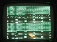
And Success! We are running the PET TEST and the results are. Well, i doesnt pass the first test if read the documentation right. Ill add a picture. I hope the resolution is high enough.

PETTEST2.gif

but thats pretty awesome.

SkyCaptain
 
Check the user manual to interpret the information. The manual can be found here: https://drive.google.com/drive/folders/1fyLbr1kcG98a2FDOMo1H5pj9lIdJpHcx

Daver2 will tell us more but it looks like some errors in low RAM.

Your RAM are on sockets so perhaps replace the 4116 or equivalent RAM chips on row I2 through I9 to start. Or possibly you may have some bad sockets or contact. Have you reseated the RAM chips? You can perhaps spray contacts with contact cleaner and push chips down firmly into the sockets. Let's see what the groups says. Things are looking up!
 
Last edited:
... And i think i have found the Issue for the screen not working anymore... there are two brown cable coming off the power supply, going to the screen, and one of those cables has detached from the power supply. The other one is still attached so i hope with some schematics over at zimmers i will find out which cable this is and reattach is to the power supply.
The two brown wires running up to the monitor are AC from Pins 7 and 8 on the transformer, but it might depend on the model and screen size.
Should be ~15V AC on my 9" screen PETs
 
And Success! We are running the PET TEST and the results are. Well, i doesnt pass the first test if read the documentation right. Ill add a picture. I hope the resolution is high enough.
...
G means good. B means bad.
The dots are good. The ones that are not dots are bad and what's displayed is what was read back from that location instead of the expected value.
It should be all GGGGGGGGGGGG and all .......................
The position of the non-dot characters should in theory correspond with the position of the Bs above.

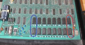
In any case, you have bad RAM in the first 512 bytes and you'll need to replace the RAM in column 1
You can quickly swap the chips in column 1 with the two chips in column 8 or any of the others. Once you have two good ones in the first column, it should pass that test and boot up to basic.
tempsnip.jpg

Unless of course the problem is actually with the socket or the 6502.
I had a 6502 once that would do this. It worked but appeared to have bad RAM. The RAM was fine the CPU was bad. It could read fine but apparently couldn't reliably write to ram all the time.

TIP: I use he video ram chip sockets to sort out which ones are good and which are bad. Once you have the system starting, you can swap the others one at a time into VRam and you can see right away if they are bad.
 
Last edited:
Yes, no power supply = no picture...

Hutch is spot on with the low RAM fault.

RAM replacement time...

By looking at the PETSCII code for the characters that are displayed with a ‘B’ cell, and the address it occurs at, you should be able to work out which bit(s) are faulty. However, sometimes it is just easier to move chips around (especially if they are in sockets). However, keep a note of which chips you try where...

After that test it will move on and test the ROM checksums (everything except the EDIT ROM of course) and you can also test the keyboard. After that, it will perform an exhaustive RAM test for you.

Dave
 
Last edited:
In any case, you have bad RAM in the first 512 bytes and you'll need to replace the RAM in column 1
You can quickly swap the chips in column 1 with the two chips in column 8 or any of the others. Once you have two good ones in the first column, it should pass that test and boot up to basic.
View attachment 61448

Hutch,
This PET has the 4116 dynamic RAMS. One needs eight good chips in the I row to get to boot.
 
OK, thanks, i thought i understood that much. But after reading the following comment by dwight "On the Pet, the ROMs have some of the address decoded by the combinations of high and low select pins. This makes it a pain for us hobbyist that wish to use standard EPROMs in place of the ROMs. It requires extra circuits put on adapter boards. An alternate is to replace several ROMs with a single large size EPROM." i was under the impression that there was a little bit more going on with an original ROM compared to a burned EPROM, regardless of if it was a 2732 or a 2532.

I see the confusion, but there Dwight was referring to the very first PETs that used the 6540 ROMs. It came in an odd 28 pin package that allowed for several chip selects with both high and low enables. Your version of PET uses the 24 pin 6332 ROM that is pin compatible with the Texas Instruments 2532 EPROM or equivalent.
 
I see the confusion, but there Dwight was referring to the very first PETs that used the 6540 ROMs. It came in an odd 28 pin package that allowed for several chip selects with both high and low enables. Your version of PET uses the 24 pin 6332 ROM that is pin compatible with the Texas Instruments 2532 EPROM or equivalent.

Thanks for the correction. I get these different Pets mixed up easily.
Dwight
 
Hey guys, im back. Sorry there was some family drama I had to deal with last week, but everything is on track again so im can go back to looking at this little project.

Anyways, the ram is bad. First i will remove the 2nd row of RAM chips and try to boot. If that fails, ill try to replace enough chips to get 8 working ones in the 1st bank.
One thing i can say is that the RAM has been resocketed. and the soldering work by who ever did it, looks pretty nasty. I dont know though if there is any faults because of that. I can post pictures of it if you guys want.

SkyCaptain
 
Back
Top