Ansgar Kueckes
Member
- Joined
- Feb 11, 2024
- Messages
- 40
Oops, message accidentally deleted, here again:
Found the hi-res schematics for Rev D board 2 here: https://deramp.com/downloads/mfe_archive/010-S100 Computers and Boards/00-Cromemco/10-Cromemco S100 Boards/Dazzler/Manual/Dazzler Rev D/197811 023-0003 Dazzler 1978-11 Schematic 2.jpg
And the hi-res scan of the manual (includes the foils) here: https://deramp.com/downloads/mfe_ar...Manual/Dazzler Rev D/Dazzler Rev D Manual.pdf
I'll use both for the KiCAD version.


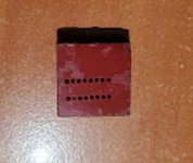
") after I messed up my first attempt I actually went back and read what you had wrote (back on like page 8 or so). I had made other IDC ribbon cables before so thought these would be no big deal. I actually ended up using a small block of hard rubber. I used my broken connector to push into the rubber to create the holes, then put in the new socket and pressed with a vice - worked perfectly.
after I messed up my first attempt I actually went back and read what you had wrote (back on like page 8 or so). I had made other IDC ribbon cables before so thought these would be no big deal. I actually ended up using a small block of hard rubber. I used my broken connector to push into the rubber to create the holes, then put in the new socket and pressed with a vice - worked perfectly.
 that worked out perfectly. This is why I never throw out anything in my parts bins.
