• Please review our updated Terms and Rules here

Cromemco dazzler replica project

Yes, KSCOPE and GDEMO initialise the Dazzler correctly.

One of the early tests is to output 80 to port 0E (O 80 0E) and look for activity on the internal latch on the Dazzler. I will post where to check for you tomorrow.

If the card is not linked properly for ports 0Eh and 0Fh we are not going to get anywhere fast!

J1 to J1 etc. should link the card for the correct I/O ports by default.

Dave
 
Last edited:
Try the following as a test to make sure that the Dazzler is addressed correctly:

Monitor IC48 pin 8 with a logic probe. The level should be LOW.

Enter the RDOS command "O 80 0E".

You should observe a low-high-low pulse.

Monitor IC48 pin 6 with a logic probe. The level should be LOW.

Enter the RDOS command "O 00 0F".

You should observe a low-high-low pulse.

Monitor IC42 pin 12 with a logic probe. The level should be HIGH.

Enter the RDOS command "E 0E".

You should observe a high-low-high pulse.

Dave
Thanks, wanted to carry this out yesterday but was feeling under the weather.

IC48 pin 8 is low, after entering "O 80 0E" I observe no pulse or activity on this pin.

IC48 pin 6 is low, after entering "O 00 0F" I observe no pulse or activity on this pin either.

IC42 pin 12 is high, after entering "E 0E" I again observe no pulse or activity on this pin. Tried this twice, first time "E" result as "3F", 2nd time result was "7F".
 
Ah, so your address decoding links are possibly not correct (J1 to J1 etc.). Either that or you have a faulty IC somewhere in that short chain of logic.

With the address decoding incorrect - you are going to get absolutely nowhere!

Dave
 
You could move back and measure IC48 pin 11 whilst performing an "O 80 0E" RDOS command.

See if you observe something then?

Dave
 
The S-100 address bus is active HIGH.

So, to decode for I/O ports 0E and 0F requires:

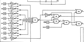
A7 = 0 - This requires that the input to IC45 be connected to the output of the inverter gate via the link matrix.
A6 = 0 - This requires that the input to IC45 be connected to the output of the inverter gate via the link matrix.
A5 = 0 - This requires that the input to IC45 be connected to the output of the inverter gate via the link matrix.
A4 = 0 - This requires that the input to IC45 be connected to the output of the inverter gate via the link matrix.
A3 = 1 - This requires that the input to IC45 be connected to the input of the inverter gate via the link matrix.
A2 = 1 - This requires that the input to IC45 be connected to the input of the inverter gate via the link matrix.
A1 = 1 - This requires that the input to IC45 be connected to the input of the inverter gate via the link matrix.
A0 = don't care for the address decoding purposes.

The output of IC45 (on pin 8) should be HIGH if the Dazzler is not selected and should go LOW when the Dazzler is selected. For a NAND gate (IC45) this means that all of the INPUTS should be HIGH to give a LOW output.

Note that the address bus is not qualified by the SOUT and SINP signals - so we could get some false triggers arising as a result.

Dave
 
The output of IC45 (on pin 8) should be HIGH if the Dazzler is not selected and should go LOW when the Dazzler is selected. For a NAND gate (IC45) this means that all of the INPUTS should be HIGH to give a LOW output.
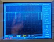
Ok then this is really strange because on IC45P8 I am seeing this pulsing activity, the freq bounces around so its not a stable wave. But issuing "O 80 0E" and "O 00 0F" doesn't change the behavior. Maybe it's possible I put the wrong IC in the wrong socket or something. I going to go through and double-check everything.
PXL_20240317_172721794~2.jpg
 
I have just manually checked the PCB layout for board 2 and J1-J7 look correct to me.

Might also be worth checking IC45 pin 12 to see what the logic level is. I would have thought it should be HIGH.

You can check the output from IC45 as well on pin 8. Make sure the pin is not oscillating under normal circumstances and then see if it pulses when you enter the RDOS command "O 80 0E".

Dave
 
STOP please!

If you are getting some output from IC45 on pin 8 it means that the logic is actually working.

However, the output from IC45 pin 8 can operate for a number of reasons because the CPU is actually operating and we are only looking at part of the problem (i.e. address lines A1 through A7).

Can I suggest putting IC48 pin 13 (SOUT) on your oscilloscope as well. See if any of the LOW pulses on pin 8 align with concurrent activity on SOUT?

If you have constant activity on IC45 pin 8 - in reality you are never actually going to identify the one pulse that occurs from your RDOS command!

Dave
 
Might also be worth checking IC45 pin 12 to see what the logic level is. I would have thought it should be HIGH.
It is high and remains high.

You can check the output from IC45 as well on pin 8. Make sure the pin is not oscillating under normal circumstances and then see if it pulses when you enter the RDOS command "O 80 0E".
IC45 P8 is oscillating at power on, nothing changes after issuing the commands.

Can I suggest putting IC48 pin 13 (SOUT) on your oscilloscope as well. See if any of the LOW pulses on pin 8 align with concurrent activity on SOUT?
IC45 P13 just remains LOW, no activity before/during/after the commands.

I have confirmed all my IC's were inserted correctly :)
 
IC45 pin 13 is not actually connected inside the IC!

It should not (therefore) be LOW - a logic probe should identify it as "no connect".

This is a shortcoming of using a multimeter or an oscilloscope. Sometimes they do not tell the truth and requires the human to read the datasheet for the IC!

Dave
 
Got the trigger condition... Chocolate cake clearly helps!

You need to use both channels of your oscilloscope in CHOP mode.

Set up your oscilloscope to trigger on a HIGH to LOW transition of IC45 pin 8 with one channel.

Use the other channel to probe the address lines (A1 to A7) of the S-100 bus. You can use the inputs to the inverter gates if you wish.

With IC45 pin 8 LOW - look at the state of each of the address lines A1 through A7 in turn and note whether the address line is HIGH or LOW.

A7 through A4 should be LOW.
A3 through A1 should be HIGH.

If one (or more) of the address lines is not as specified above - or if it is both HIGH and LOW when IC45 pin 8 is LOW - then we can look at these address lines in more detail.

Just going out for my evening walk (while there is a bit of daylight left)...

Dave
 
Incidentally, you will have to adjust the timebase to zoom in on the low-going trigger pulse from IC45 pin 8 to make any sense of the address line!

A narrow pulse (as you currently have - post #390) is of no use. The oscilloscope trigger should help to isolate one pulse and make it stable on the screen for meaningful address line measurements.

Dave
 
Got the trigger condition... Chocolate cake clearly helps!

You need to use both channels of your oscilloscope in CHOP mode.

Set up your oscilloscope to trigger on a HIGH to LOW transition of IC45 pin 8 with one channel.

Use the other channel to probe the address lines (A1 to A7) of the S-100 bus. You can use the inputs to the inverter gates if you wish.

With IC45 pin 8 LOW - look at the state of each of the address lines A1 through A7 in turn and note whether the address line is HIGH or LOW.

A7 through A4 should be LOW.
A3 through A1 should be HIGH.

If one (or more) of the address lines is not as specified above - or if it is both HIGH and LOW when IC45 pin 8 is LOW - then we can look at these address lines in more detail.

Just going out for my evening walk (while there is a bit of daylight left)...

Dave
Thanks, really appreciate the help on this. Would you be willing to hop on a call with me? the scope setup here goes a little beyond my skillset. :)
 
Set your oscilloscope up as in post #390 (with channel 1 connected to IC45 pin 8).

Enable channel 2 and connect channel 2 to A7 (IC59 pin 9).

We can take it from there...

Dave
 
Probably a bit late tonight...

What is confusing you?
Not a problem just thought I'd offer in case it made it easier.
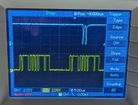
The trigger stuff always confuses me a bit. I'll take a picture and you can tell me if this looks right:

Channel 1 is on IC45P8, Channel 2 is on IC59P9
PXL_20240317_191010489~2.jpg
 
Back
Top