• Please review our updated Terms and Rules here

Cromemco dazzler replica project

You might be surprised. There isn't any Black magic, only Science and it is not a Rathole either

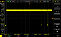
Okay, but… the whole thing kicking this off was a question about an overshoot on the square wave observed on the scope, and that appears to have been resolved by changing the probe setup. I’m by no means an expert, but that looks like a decent square wave to me now.

Maybe I’m looking at the wrong IC14, but on the Dazzler schematic I pulled up it looks like this point that’s being measured is after the raw output from the colorburst crystal used for master timing is inverted twice; both phases are used, with the un-double-inverted phase providing the main clock signal and this double-inverted one driving some of the final color output. I guess the question I have here is this: what is the working theory you have for the *very small* difference in propagation delay between straight TTL and LS causing some kind of downstream problem? I could maybe see this causing a slight phase shift in the color, maybe, but… do you think it’s not driving the main timing chain “hard enough”?

(I mean, if you really think that little bit of drive you get from straight TTL is such a huge deal for this part of the circuit you could slap a couple weak pull-ups on the two clock phases and see if things just magically get better. Not seeing that as likely, but that would essentially paper over almost all the measurable differences.)

I dunno, it just seems to me that a skipping vertical sync signal is orders of magnitudes removed from this crystal output. You could be missing a *lot* of 3.5something mhz pulses and still be dead on for something that happens *every 1/60th of a second*. And besides, the video output otherwise looks pretty good?

So yeah, feels a lot like a rathole.
 
Last edited:
If I could summarize where the original poster (Hoimes) is currently at - the IC used in the 3.58MHz oscillator, and the IC that oscillator is directly driving, have both been replaced by those originally specified. The scope tracing shows a pretty clean 3.58MHz signal coming out of the oscillator. If the video output is still unstable, something else is going on.

Yes, this. This thread has wasted two pages catastrophizing over phantom fake ICs because of a bad scope reading, while the actual problem that’s being observed involves circuitry on the other side of the continent from here. The troubleshooting guide says “look for a square wave here”, there’s a square wave there. Maybe it’s worth taking that as good enough until there’s an actual reason not to.
 
The question still remains though as to what happens when an unconnected clip is placed on test point "V" (thus adding a small antenna). Does this still "fix" the problem or not? Originally, this "fixed" the problem, thus indicating that we are talking about minutes changes in a parameter switching us from a non working board set to a working board set.

Hence the "rabbit hole" to put things back to the originally specified parts.

Dave
 
Originally, this "fixed" the problem, thus indicating that we are talking about minutes changes in a parameter switching us from a non working board set to a working board set.

I mean, sure, you can invoke some mysterious forces related to IC process here and block on that until you’ve spent infinite money on new parts, but… I’d still like to know what the operative theory you’re operating under here is.

If there really is a relationship between hanging the clip off that one point and the stability of the board it seems just, if not more, likely, that there could be some analog instability at work with a bad soldering joint or something that clipping a lead on just coincidentally settled down.
 
>>> I mean, sure, you can invoke some mysterious forces related to IC process here and block on that until you’ve spent infinite money on new parts, but…

That is not what I am saying. I am asking a question that if you perform the same test - hanging the same probe clip off the same pin - does it still appear to fix the problem or not. No more, no less.

That was the first assumption, especially as the part that was fitted is different to what was specified by Cromemco in the parts list. But since we have potentially ruled that out now...

Dave
 
The question still remains though as to what happens when an unconnected clip is placed on test point "V" (thus adding a small antenna). Does this still "fix" the problem or not? Originally, this "fixed" the problem, thus indicating that we are talking about minutes changes in a parameter switching us from a non working board set to a working board set.

Hence the "rabbit hole" to put things back to the originally specified parts.

Dave
This was the issue in that adding the wire altered the instability. A wire might be around 10pF if you are holding the insulation, if not it might be less than 5pF. A x10 scope probe could be in the order of 30 to 75pF depending on the type.

Maybe a coincidence as Eudi suggested, but it should be re-checked. It must be a very borderline condition.

I'm more suspicious of the crystal oscillator circuit itself. The measurements on it that appear stable, it may not be when the measurements are not being made. If there is a borderline condition, loading it with the test probe or even the buffers after it will result in some additional loading.

(you might think that after a buffer or two, the oscillator would not be affected by loading on the output of those buffer gates, but it is, if you want proof of this, set up an RF oscillator and frequency counter with six buffer IC's in series and load the final one, you will see a shift in frequency. I spent many years making buffers for local oscillators in radios so that output loading had no measurable effect on the frequency, the only way to get perfect isolation is with an optical link)

The question I would have is, when the oscillator is being tested either directly or after a few gates, is the circuit stable then ? If it is, I think the oscillator should be suspect and the 74ALS04 there should be replaced with the 74LS04 and a new/different crystal should be tried too.
 
You might be surprised. There isn't any Black magic, only Science and it is not a Rathole either (though I am a major fan of the Rat and think every laboratory should have one as a Mascot). Even in the early days of TTL this caused problems (chaos), with plausible subtle variations of TTL IC's, for example the 7493 and the 7493AN (let alone what might happen with an LS or an ALS part) Check out page 10 of this document under the topic "the weak net bug" :

www.worldphaco.com/uploads/ARCADE_MINI-PONG.pdf

The propagation times along flip flop chains, in non synchronous counter systems become cumulative.

In any case, despite that, the input pin current, mostly won't have a huge effect, unless say, you are using the IC in a non standard way. A good example is when you turn an inverter into into an analog amplifier by placing a feedback resistor from its input to its output. Then, all of a sudden, the input current is a critical factor which in a cmos part is so negligible you might require a 1M Ohm resistor, but in a 74xx part 330 Ohms.

In addition, it pays to remember that Quartz crystals are "tricky" they can have parallel and series oscillation modes and overtone modes, and in some circuits if the crystal is not suitable jump between these creating instability that way.

All of the above was why I sought to use original chips in my Dazzler and sought out an original style crystal too.

Also as noticed, standard TTL has good current sinking ability and poor current sourcing ability. If the part you have bought is a cmos substitute, re-labelled, the result you get might not be entirely suited to the circuit, especially if small capacitors have been added to delay a pulse, because the source resistance driving the high or low doesn't match the original part.

The Designers off the Dazzler knew all of the above, so this is why they specified exact parts.And why if you use these, you don't run into any issues.

Posting #1251 - Holmes stated the ALS04 was replaced with an LS04 (as specified in the original design) and it did not solve the problem.
 
FWIW, an iffy crystal smells like a real possibility to me. I’ve seen some strange voodoo with oscillators, like just touching the case, or even being near it, changes how it behaves.
 
Yes, your hand is a capacitor plate, and a very good source of 50Hz/60Hz electrical noise.

Yep. And again, this at least makes electrical sense, unlike the “chip is the wrong process” theory.

(I get the idea that on a holistic level you would ideally build the circuit as exactly as described if you want exact “authentic” behavioral characteristics, but on an individual level it seems like it’s worth considering what a given chip *does* in the circuit and if those changes could realistically cause problems. C14 is in a kind of interesting spot in one sense, because half of it is used as inverters in one of the fastest parts of the circuit, and the other two NAND gates are in much slower roles, but in either place I don’t see where the difference in speed between any of the common processes would realistically matter.)

Devil’s advocacy, here, but… I think you might actually improve the reliability of the oscillator circuit if you used a CMOS 7404? An interesting thing I found while repairing a TRS-80 was Radio Shack actually used CMOS strategically in a few sections of the video output that relied on RC delay circuits because of their more predictable switching thresholds…
 
Yep. And again, this at least makes electrical sense, unlike the “chip is the wrong process” theory.
The only thing going against that theory is that the circuit was malfunctioning without any additional attachments that would capacitively introduce external noise producing a malfunction, and it stopped malfunctioning with a wire attached. Indicating that there is some intrinsic instability going on and the additional capacitance was not introducing a problem or noise, it was helping to suppress a problem.

Clearly with the small capacitances involved, it must be a high frequency issue. As I mentioned we know that the pcb design works, and if the power supply distribution is ok and bypassed properly, then it only leaves the chips. Even with errors such as an input pin left open (say forgotten to be soldered) that is supposed to be tied high, normally TTL are quite noise immune because the input pin voltage goes well above logic high. But worth checking for that. And we do know for sure that with the original family of chips at least the circuit is stable. So I cannot see that it is unreasonable to at least fit the original family of chips throughout both boards, and re-test it. Currently there is no other explanation why the circuit was malfunctioning and sensitive to a small added capacitance. And as far as I know, all other Dazzlers built with the original chips haven't had this sort of issue. Looking at both boards there area number of LS parts fitted to both boards where they were supposed to be be plain 74 types. And I know that most of the time, this is ok and all that happens is reduced power consumption, however in some cases it can give troubles. Especially video speed circuitry.

Speaking of chip incompatibilities(if you believe in them at all) Silicon Chip magazine recently did a clone project of the Stylophone using a 555 chip. They were worried that different chips could result in different audio output frequencies and foul up the tuning. So they went down the Rabbit hole and bought a lot of different 555 variants to test. They could not find any differences (in their circuit) all chips obeyed the same equation and acted identically. Yet, in another type of circuit, Atari's pong where a 555 is used to control the position of the paddle, out of all the 555's in the world, the only one that works correctly in that specific circuit is the NE555N. I found this out using alternate 555's. The NE555E, all cmos variants of the 555, don't work correctly, it is not that they don't work at all, but they have a linearity issue that results in inadequate range and poor linearity of the control of the paddle position on the screen and the differences only show up in that particular application. Probably there are thousands of applications where tiny differences in chips have little to no effect at all, but in some other applications they do.
 
Last edited:
identically. Yet, in another type of circuit, Atari's pong where a 555 is used to control the position of the paddle, out of all the 555's in the world, the only one that works correctly in that specific circuit is the NE555N. I found this out using alternate 555's. The NE555E, all cmos variants of the 555, don't work correctly, it is not that they don't work at all, but they have a linearity issue that results in inadequate range and poor linearity of the control of the paddle position on the screen and the differences only show up in that particular application

So… this is pretty much exactly what I was talking about when I said that you have to think about what the chip is actually *doing* in the circuit. When you’re using a 555 to read a paddle the *analog* characters of the process are going to matter. (The 555 is intrinsically a semi-analog component.) So, sure, if you were working on a joystick port input or something then maybe you should immediately suspect a problem like this…

But the 7400 at C14 is, at least so far as the clock generation is concerned, 100% acting in a digital role. It needs to go up, and it needs to go down. That’s it; as long as it’s generating enough output drive to trigger the next thing in line that should be it, right? (The other two gates on it *are* being used to drive resistors on the final output mixer, so you could potentially need to tweak the resistor values if you, say, subbed a CMOS variant that drove closer to the rails.)

If you really want to suspect a flaky chip in this area I’d point at the 74LS04, but like I said, my reasons for it would be that TTL chips aren’t great at the task it’s being asked to do here, which is essentially turn a sine wave into a square wave. CMOS tends to be more reliable in this role because they have sharper cutoffs between “off” and “on” and are generally more noise tolerant…

But yes, the circuit should work as designed, so my money would actually lean towards a flakey crystal rather than a bad chip.
 
But the 7400 at C14 is, at least so far as the clock generation is concerned, 100% acting in a digital role. It needs to go up, and it needs to go down. That’s it; as long as it’s generating enough output drive to trigger the next thing in line that should be it, right? (The other two gates on it *are* being used to drive resistors on the final output mixer, so you could potentially need to tweak the resistor values if you, say, subbed a CMOS variant that drove closer to the rails.)
The thing is though, the problem does not have to be very near where it was noticed that the connection to a wire stopped the problem. We already know changing the clock IC had no effect nor the 7400 nearby, which as you remarked regardless of its properties have a fairly simple digital role. It is elsewhere after counter chains and other other pulses with timing considerations have to be correct, that a problem could crop up. Most of the issues I have seen occur when a pulse arrives at a borderline time with respect to another at the inputs to a gate or flip flop/counter, and the output is either a runt pulse or the flip flop doesn't trigger reliably, or at all. In other words, currently I think nobody is sure which part of the circuit was malfunctioning or why and it could be on either of the two boards. It was just guesswork about the 7400 and the oscillator.

Cmos gates do make better oscillators, the feedback resistors can be very high and it makes the cmos inverter gate behave as a very high Z in, low Z out amplifier, which works well with crystals.
 
If @Holmes has a spare of the 3.58Mhz crystal that’s probably what I’d try next if we were taking the shotgun approach to this. My anecdotal experience involves a big pile of cheap AliExpress crystals that I was using for some video experiments (trying different pixel clocks, etc), and I definitely found out of a random batch some were more stable than others.

This circuit is actually a little weird how it uses the 7404 for the two inverters inside the oscillator, but pins 11-13 of the 7400 for the “final drive” inverter. There shouldn’t be anything *wrong* with that, per se, but it’s still… odd? What does the waveform look like on pin 11, and does clipping the probe there also stabilize it? (If the scope has two channels pins 3 and 11 should be exact inverses of each other, with only around 15ns offset with an LS.)
Finally got round to digging out my N* and just noticed it has 64K of static RAM, rather than the dynamic RAM I was expecting, so that might mean I can start making one now.
 
Back
Top