• Please review our updated Terms and Rules here

Exidy Sorcerer 1: Noisy power supply

robjordan

Member
Joined
Aug 7, 2020
Messages
23
Location
Winchester, UK
Hi all

I'm working on my old Exidy Sorcerer. It's unmodified since my dad came home with it in 1979. It works, but I'm noticing there seems to be a lot of high frequency noise on the power supply, and also on the tape MIC and AUX outputs, which I'm guessing is a consequence of the power supply noise. I'm a novice and I don't know what is a normal amount and frequency of noise for a linear-regulated supply of this vintage. I took some scope pictures to illustrate.

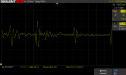
5V rail: Mean: 4.8V, Pk-Pk over a couple of seconds 1.2V, stddev: 70mv.
5V-noise.png

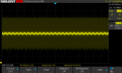
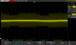
12V rail: Mean: 11.6V, pk-pk over 15ms: 784mV
12V-noise.png

AUX out 1200 Hz tone, amplitude is 216mV with about +/-50mV noise either side of the signal.
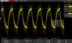
AUX-out-noise.png

The MIC out signal, which is only meant to be 50mV, seems totally drowned in noise.

I'm guessing this isn't normal, and that some re-capping will be needed. I ran a leakage test on the gigantic 8000uF capacitor, which is easily-removed. It didn't indicate any significant leakage to the best of my understanding (leakage current @ 15V was about 30uA after 5 minutes and then slowly reduced to 20uA.

Should I replace all the caps in the PS, or is there a way I can diagnose the source of the problem?

Incidentally, does anyone ever replace the linear power supply with a switched-mode one, or would that be sacrilege? It runs incredibly hot, even - I discovered after leaving it plugged in one night - if the power switch in the system unit is turned off, which I don't really understand as the schematics show the power switch disconnects the transformer primary. Could there me a fault in the power line filter?

I should add it's a 240V/50Hz model. Schematic for the power supply here in case it's helpful.

Rob
 
Hi all

I'm working on my old Exidy Sorcerer. It's unmodified since my dad came home with it in 1979. It works, but I'm noticing there seems to be a lot of high frequency noise on the power supply, and also on the tape MIC and AUX outputs, which I'm guessing is a consequence of the power supply noise. I'm a novice and I don't know what is a normal amount and frequency of noise for a linear-regulated supply of this vintage. I took some scope pictures to illustrate.

5V rail: Mean: 4.8V, Pk-Pk over a couple of seconds 1.2V, stddev: 70mv.
View attachment 63062

12V rail: Mean: 11.6V, pk-pk over 15ms: 784mV
View attachment 63063

AUX out 1200 Hz tone, amplitude is 216mV with about +/-50mV noise either side of the signal.
View attachment 63064

The MIC out signal, which is only meant to be 50mV, seems totally drowned in noise.

I'm guessing this isn't normal, and that some re-capping will be needed. I ran a leakage test on the gigantic 8000uF capacitor, which is easily-removed. It didn't indicate any significant leakage to the best of my understanding (leakage current @ 15V was about 30uA after 5 minutes and then slowly reduced to 20uA.

Should I replace all the caps in the PS, or is there a way I can diagnose the source of the problem?

Incidentally, does anyone ever replace the linear power supply with a switched-mode one, or would that be sacrilege? It runs incredibly hot, even - I discovered after leaving it plugged in one night - if the power switch in the system unit is turned off, which I don't really understand as the schematics show the power switch disconnects the transformer primary. Could there me a fault in the power line filter?

I should add it's a 240V/50Hz model. Schematic for the power supply here in case it's helpful.

Rob

Hi Rob,

I have one Sorcerer that has a switchmode power supply mounted under the lid - never seen another one like it though. The holes through the case do look sacrilegious but as it is a vintage customisation it is fair enough - this machine also has an internal FDC so it is quite neat.

Personally I would not do that myself to a vintage Sorcerer today - they are far too rare to be hacking up.

To lower the heat output by the linear PSU Dyne Industries in Melbourne developed a replacement transformer that was more efficient. It was a reasonably popular upgrade here and 76 of them were sold. Dyne could still make one up for you to their original plans. Price would be AUD150 plus quite a bit of freight to the UK. A number of people here also elevated the large wirewound resistor off the PSU PCB (on the Mk II) using short lengths of paper clip wire.


I have been struggling for a while to get accurate data on what the ripple should be on the PSU. People tend to just replace the capacitors without characterising them first. You will probably find the middle size electrolytic is bulging and dried out at least. Whether this is contributing to the noise you are picking up on the MIC output I don't know. Mine seems pretty clean but I have noticed a lot of noise on the AUX output. In terms of the latter a recently unearthed a newsletter article that makes me wonder if all the 'ground' pins on the cassette/serial port are really all connected as shown on the schematic.
 
A linear supply should show no high-frequency noise. Have you tried running the system temporarily from a different PSU?

By the way, what's the frequency of the noise? Looks pretty high.
 
Hi Rob,
Personally I would not do that myself to a vintage Sorcerer today - they are far too rare to be hacking up.
Hi exidyboy, Yes, I feel so too. Just need to keep my hands away from hot components while I work on it with the lid off! One minor burn already and, separately, a 240v zap from the terminals of the power supply filter, which are rather exposed. Or were, I've taped a big piece of rubber over the top now to avoid a repeat. [After I posted that it gets hot even when turned off, I checked because it seemed so unlikely based on schematics. It doesn't. I figure it must have just retained a lot of heat overnight. There's a lot of thermal mass in that transformer.]
I have been struggling for a while to get accurate data on what the ripple should be on the PSU. People tend to just replace the capacitors without characterising them first. You will probably find the middle size electrolytic is bulging and dried out at least. Whether this is contributing to the noise you are picking up on the MIC output I don't know. Mine seems pretty clean but I have noticed a lot of noise on the AUX output. In terms of the latter a recently unearthed a newsletter article that makes me wonder if all the 'ground' pins on the cassette/serial port are really all connected as shown on the schematic.
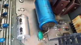
I think you're talking about the one which is 2200uF on my system board, and the same in schematics, though, confusingly, it's listed as 1500uF in the Technical Manual. It does seem to have some bulging crust at the anode. I've ordered a replacement.
2200u-cap.jpg
Rob
 
A linear supply should show no high-frequency noise. Have you tried running the system temporarily from a different PSU?

By the way, what's the frequency of the noise? Looks pretty high.

Thanks Chuck. Naive question. Some of the regulator output pins are quite hard to access. Can I just clip leads from a separate PSU onto any convenient exposed bits of the +5/-5V/12V rails? Will the potentially failed capacitors have any influence on the power delivery in that scenario?

Yes, the noise frequency is very high. I haven't looked at it with FFT but you have to zoom in a long way to see anything like a repeating pattern. This trace appears to show a pattern at around 4MHz. The hardware frequency counter registers around 9-12Mhz on the 5V line. Does that give any clues to the likely cause. Is it perhaps more likely failed low value capacitors?
SDS00005.png
 
If you have the ON/OFF switch turned OFF, there should be no current flow at all in the power supply. It should be as simple as that. If there is still some current flow somewhere, your power supply primary is not wired up as per the schematics. This should be relatively simple to check with a multimeter.

Remove the fuse from Exidy fuse holder and check (with a multimeter set to a low resistance range) that there is continuity from the live of the plug to one side of the switch and that the switch actually works when it closes and opens (again, measure the resistance across it). Measure the resistance from the live pin of the plug to the side fo the fuse holder that should be connected to the incoming mains live. Ensure that this circuit is made when the switch is CLOSED/ON and open circuit when the switch is OPEN/OFF. You should measure a high resistance between the live and neutral pins of the plug with the ON/OFF switch either way round (as we have the fuse removed).

Check the wiring of the transformer primary. For 240 Volts (UK) both transformer windings should be in series with each other and one side of the transformer primary winding connected to the other pole of the fuse holder and the other side of the transformer winding should be connected to the mains neutral.

If you re-insert the fuse into the Exidy and turn the ON/OFF switch OFF. Connect your multimeter between the LIVE and NEUTRAL pins of the mains plug. Do NOT hold the wires for this test. Either use crocodile clips (or similar) if you have them or clothes line pegs if you don't. You should observe a very high resistance. Turn the ON/OFF switch to ON. The resistance should come down to quite a low value. Turn the switch OFF again. The resistance should return to a high value again.

With the ON/OFF switch ON, measure the resistance between the live and earth pin of the plug and then between the neutral and earth pin of the plug. In both cases you should read a very high resistance.

If these testa are OK, I don't see where your 'heat' is coming from.

If you have access to a PAT tester (sic) you could perform an insulation test (at 250 V) and an earth leakage test to see if there is anything untoward.

Your high-frequency noise would not be caused by the large capacitor but by all the failing low-valued decoding capacitors or the voltage regulators themselves.

A fault in the power line filter shouldn't cause any current flow in the transformer if the power switch is OFF...

Two words of warning:

1. These tests are to be performed with the Exidy NOT connected to the mains at all.

2. If you measure the resistance of the transformer primary winding - and cause current to flow through the winding - when you break the current, a high voltage will be developed across the winding as the magnetic field collapses. If you are holding the multimeter probes at this time, you will get a small electric shock. Keep fingers well away!

Dave
 
Last edited:
It is possible that the regulator is failing. If it is on the edge of thermal shutdown or current limit, they can oscillate. 1.2KHz is within the range that is can oscillate. It is unusual but can happen.
I see that there is a shunt resistor. Disconnect a lead of the resistor and check that it is within spec. The purpose of the resistor is to bypass some of the current load. You should not run the power supply without a load. This can damage the regulator, when there is a shunt resistor.
What Dave is saying is that it is more likely the 6.8uf capacitor than the primary filter cap, at that frequency.
Dwight
 
Last edited:
Dave

Thanks for your very clear testing instructions. With your help I have discovered that it seems live and neutral were reversed in the mains plug. The mains cord has no colour-coding on live and neutral, just green for earth, and a textured black and a smooth black insulation sheath. Following the wiring, and using the continuity tests you described, I can see that the smooth wire is connected first to the fuse, then through the fuse to the switch and then presumably to the transformer. I confirmed this with continuity from (now correctly-wired) Live pin to fuse. Switch contacts are quite well sheathed, so I wasn't able to confirm continuity onward through fuse to switch, but I can see the connecting wire. And I can confirm that there is no continuity from Live to Neutral pins of the mains plug with the switch off, but with the switch on, there is a 16 ohm resistance, through the transformer primary I assume.

Now I've swapped the mains leads, I believe things are correct. I haven't turned back on again out of abundance of caution. If I've misinterpreted please shout!

Must have been wired this way for 40 years. Amazing!

Is it surprising or significant that the fuse sits between mains and switch, rather than between switch and transformer, as I think your procedure implies?

Rob
 
The mods appear to have let you fly unhindered now...

The wiring colours are for the other side of the Pond. Someone has obviously put a UK plug on an American machine (and got it wrong)...

FYI: I always use a residual current circuit breaker in the main wall socket when playing around with anything. That way I get to live... Suggest you invest in one also!

I was assuming the schematic diagram is correct (Mains Live -> Filter -> Switch -> Fuse -> Transformer -> Filter -> Mains Neutral). Perhaps I didn't explain it too well.

Having the mains live connected to the transformer (and not going through the switch) is a major sin by the previous owner.

The idea of having the switch in the live side 'upstream' of the fuse is so that you don't get a shock if someone leaves the Exidy pugged in to a live socket (Doooo), but with the ON/OFF switch OFF whilst they are changing a blown fuse in the Exidy. Of course, that would be a stupid thing for someone to do, as they should always disconnect the equipment from the mains socket before doing such a thing shouldn't they...

Yes, the 16 Ohms or so will be the DC resistance of the primary winding.

Having the live and neutral swapped over shouldn't be causing your overheating if you leave it plugged into a wall socket. However, have we now discounted that from a previous post?

Dave
 
Er, yes, bulging electrolytics are not good - they tend to go BANG and let the black smoke out of the box...

Please replace that before switching it on again.

If you have any bulging (or leaking) electrolytics, please replace them before ever powering up.

I have had a few go BANG on me in my time - and a few tantalum beads as well. They frighten the 541t out of you!!!

Dave
 
Hi exidyboy, Yes, I feel so too. Just need to keep my hands away from hot components while I work on it with the lid off! One minor burn already and, separately, a 240v zap from the terminals of the power supply filter, which are rather exposed. Or were, I've taped a big piece of rubber over the top now to avoid a repeat.
Yes the design does not meet modern safety standards. Some people cover those terminals.
robjordan said:
I think you're talking about the one which is 2200uF on my system board, and the same in schematics, though, confusingly, it's listed as 1500uF in the Technical Manual. It does seem to have some bulging crust at the anode. I've ordered a replacement.
View attachment 63070
Rob

I've never seen a Sorcerer without the mid-size cap bulging. They get very hot on both models. I have not replaced any of mine yet though because the modern ones don't look as good. I notice your Molex connector for power input from the transformer looks discoloured from the heat or is that staining from some other source?

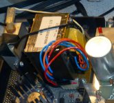
Here is a photo of the Dyne Industries transformer. The machine is in the UK but the mod was done in Australia before the owner moved. Looks like a Mk I like yours with power supply on the logic board. The core uses a different material that is more efficient and the output voltages are set to be a better match for a 240V supply.

Measuring the ripple is difficult because there is so much hash from the massive PCB and results seems highly dependent on grounding technique. I've watched some videos on power supply noise measurement but they are too detailed to be useful.

DYNE_medium.jpg
 
Er, yes, bulging electrolytics are not good - they tend to go BANG and let the black smoke out of the box...

Please replace that before switching it on again.

If you have any bulging (or leaking) electrolytics, please replace them before ever powering up.

I have had a few go BANG on me in my time - and a few tantalum beads as well. They frighten the 541t out of you!!!

Dave

I was just mentioning the use of a "dead man" switch, in one of the other threads. One could get one of those foot switches and use that to interrupt the AC when things go pop or bang. It is a lot faster to get you're foot off the switch when you hear the bang, than reaching for the units power switches.
I had a large tantalum pop and do some fire damage to one board.
Dwight
 
A linear supply should show no high-frequency noise. Have you tried running the system temporarily from a different PSU?

A little more information. I tried supplying +5V externally from a bench power supply. I wasn't sure whether anything would work without the +12 and -5 but it booted. Some shimmering on the screen, but a normal monitor prompt.

Because the LM323K is rated for 3A, I current-limited the supply to 3A. The system drew 3A. I figured if it is drawing excess current, something must be getting hot. The only noticeably hot components were three 74S241 buffer/line drivers. Their case temperature was above 60 deg C within a few minutes. Is this normal?

The noise on the 5V rail was reduced compared to the usual Sorcerer power supply. Peak-peak 200mV compared to 1V before. Stddev 12mV compared 70mV.

Would I be right in thinking that the LM323K is failing to regulate effectively because something on the system board is drawing excess current or shorting to ground? Probably one of those tantalum capacitors, I suspect.
 
buffer/line drivers will get hot (ish) in normal use. In order to drive busses 'hard' you need current.

I suspect you have got a mixture of effects happening:

1. The design was never as good as it could/should have been - so probably suffered from noise originally (a bit). We have just redesigned an 8086-2 communications card from the mid 1980s at work. We had to modify the PCB because the noise was terrible! The modern components we used were affected by the noise!
2. The components has aged - making them (a) more noisy and (b) more susceptible to noise.
3. The design margins for original designs were not as conservative as they should be now. Originally, it may have drawn 2.75A from a 3A regulator. Over time, it may have sneaked up...
4. Some of the decoupling capacitors could have gone open circuit (rather than short circuit) and they will be ineffectual as a result. Finding these devils will be difficult.

It is unlikely that a tantalum capacitor has gone short circuit! (A) the computer would not be working and (B) you would have bits of it on the ceiling, walls, floor, your eye...

Remind me, did you replace the regulators?

As Dwight has said in a previous post, it is not good to operate voltage regulators (especially old ones) at (or close to) their full rating, they can oscillate... That is also the purpose of some of the capacitors around the regulator - to stop it from oscillating (or going unstable) under certain circumstances. If these capacitors are dead (open circuit) they will not be doing their job either...

Dave
 
Thanks Dave, you are very patient with me!

I haven't yet replaced the regulators, I was trying to get a bit more insight before doing that. LM323K replacements are either (a) expensive and presumably genuine, (b) inexpensive and quite likely fake or substandard, or (c) modern, pin-compatible switch-mode equivalents. I'm quite tempted to give (c) a try. Only available from US though.

Maybe I'm chasing ghosts though. The machine is working after all. It was just seeing the amount of noise on the audio output from the tape interface that set me off on this investigation.

Rob
 
The schematic shows a shunt resistor. It will take some part of the load off the regulator. I don't know what the voltage drop is across the regulator but the resistor is a 5 ohm. If we say the input in 9V to 5V, that is 4V drop. That means 0.8 amps is going through the resistor. That would leave 2.2 amps through the regulator.
Do note what I said. Don't run a shunted regulator without a minimal load. Most regulators can be damaged by too much over voltage on the output leads. This can degrade the regulator. If you run the rest of the supply without a load on the 5V, disconnect the shunt resistor!!!
Dwight
 
The schematic shows a shunt resistor. It will take some part of the load off the regulator. I don't know what the voltage drop is across the regulator but the resistor is a 5 ohm. If we say the input in 9V to 5V, that is 4V drop. That means 0.8 amps is going through the resistor. That would leave 2.2 amps through the regulator.
Aha, thanks, I see what you mean. The system can draw more than 3A on the 5V supply while still remaining within the rating of the regulator.
Do note what I said. Don't run a shunted regulator without a minimal load. Most regulators can be damaged by too much over voltage on the output leads. This can degrade the regulator. If you run the rest of the supply without a load on the 5V, disconnect the shunt resistor!!!
Dwight
Maybe I'm misunderstanding but I don't think I have attempted to run the shunted regulator without a load. It would seem quite hard to do that without removing the regulator, since there no connector or point on the circuit where any of the three DC supplies could be detached from the load. Have I misunderstood? I did run the load without the regulator (by providing an external supply - main power supply switched off) but not vice versa. I attached the 5V external supply downstream of the shunt regulator.

Rob
 
The schematic shows a shunt resistor. It will take some part of the load off the regulator. I don't know what the voltage drop is across the regulator but the resistor is a 5 ohm. If we say the input in 9V to 5V, that is 4V drop. That means 0.8 amps is going through the resistor. That would leave 2.2 amps through the regulator.
Aha, thank you, now I get it. The system/load can draw more than 3A in total while still remaining within the rating of the 3A regulator. In fact I measured the voltage drop across the shunt: 4.3V, so another 0.9A or so.
Do note what I said. Don't run a shunted regulator without a minimal load. Most regulators can be damaged by too much over voltage on the output leads. This can degrade the regulator. If you run the rest of the supply without a load on the 5V, disconnect the shunt resistor!!!
Dwight
I believe I am heeding your warning, but correct me if I've misunderstood. It seems to me it would be practically difficult to run the shunted regulator without a load, because there is no interconnect or simple way to separate the regulator and the load, short of removing the regulator from the main board. But perhaps I'm missing the scenario you are warning about.

My test did the reverse; ran the load from external power supply, without the regulator powered. I fed in the external 5V on the load side of the shunt resistor.
 
My test did the reverse; ran the load from external power supply, without the regulator powered. I fed in the external 5V on the load side of the shunt resistor.

I'm not as sure what the effect would be on the regulator, as the input side is not powered. As for the noise, you can try adding a tantalum capacitor across the 6.8uf. It won't hurt to use a 10uf there.
As for current rating and actual usage. The regulators have both thermal and current shut downs. Most of these earlier power supplies had poor thermals. At a previous life, we were brought in to a company that was having issues because it was tripping our voltage monitor. For burnin, they put the regulators in dead short at the outputs and power them to the point that they are in thermal shut down. The board has about 300 or so TO3 regulators. The power supply is rated at 200 amps and is running close to max. As I brought the scope lead up to the board, I thought I might have a ground problem. It wasn't that. The entire burnin board was oscillating at about 1.1MHz. I don't recall what the total power was but I was surprised that the FCC hadn't made a call on them. It was several hundred watts right in the broadcast band.
For your setup, I'd replace the regulator and see what can be done to improve the thermals. I suspect it is oscillating on the edge of thermal shutdown.
Dwight
 
Back
Top