• Please review our updated Terms and Rules here

Finally, I have it. Commodore PET 2001 with blue frame but its not working

Yes, in order to fit a 2716 you will need an adapter...

This is the problem with “bit rotted” 6540 ROMs - you require an adapter when replacing them with bog standard EPROMs I am afraid.

Which RAM/ROM card do you have? Some of them have my PETTESTER firmware already installed.

EDIT: Just checked your previous posts, the Tynemouth one doesn’t I am afraid.

Dave
 
Dave, yeah, I bought the Tynemouth one because I spent a long time on his blog while trouble shooting my first PET. I thought with his blog online, i could also find enough resources on using the device. Sadly that blog has since been taken down. The device though works like a charm all the same.

The one PET that I have takes 2532 EPROMs, which I cannot burn. I got a set of those burned from someone else to make that machine work again. I did buy a EPROM burner hoping i could burn the 2532s myself but that was sadly not possible due to some technical issue of the Burner. It was not the 25V needed as the machine is capable of that.

Anyways, I can how ever burn the 2716, and 2732 EPROMS without issue.

So... time to build an adapter? This is probably not necessary if I simply want to run off the ROM/RAM board, but If I want to use the ROM on the board, I would have to.
It seems though that this isnt something trivial at all.

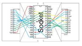
I found this website here showing the schematics for what I assume is such an adapter? http://vic-20.de/x1541/hardware/adaptors.html
but further reading indicates here (in german): https://forum.classic-computing.de/forum/index.php?thread/4369-neues-vom-6540-rom-adapter-für-den-pet2001/
that I would need a total of 3 slightly different adapters to replace all of them with standard 2732 EPROMs?

generally speaking, I would be interested in building these adapters, but I honestly have my doubts i could build all 6? that I need and still make them fit in the original position.

also on a side note, I read that these 6550 RAM chips run "toasty hot", and this is often the cause of failure for them in the long run... Mine are all still working according to the PETTESTER on my ROM/RAM board.
If I switch the board to replace the RAM, will the original RAM be used at all? like, will it get hot?

Thanks!
SkyCaptain
 
Last edited:
The 6540 ROM replacement boards have all of the additional chips on them to cover all of the bases for the number of chip select lines and their polarity.

The H3 EDIT ROM can be quite easily replaced by a 'socket sandwich' without any additional logic devices.

Only two (2) chip select lines are used on ROM H3 - and both of these are active LOW. This (conveniently) maps onto the two (2) active low chip select (or, more correctly, the chip select and output enable) lines of the 2716 EPROM).

The only question I have is around the 6540 CLK pin (pin 16) does this need to be included in the mix or not? The examples I have seen (see at the end of my post) don't use this clock signal. Technically (according to the data sheet) the addresses should be internally latched on the leading edge of the clock and the data output is only valid whilst the clock signal is high. I suspect most designs ignore this?

Wire the +5V and 0V lines up pin for pin.

Wire the data lines (D0..D7) up pin for pin.

Wire the address lines (A0..A10) up pin for pin.

Wire the PET /SELE (6540 pin 4) to the /CS line (pin 18) of the 2716 EPROM.

Wire the PET BA11 (6540 pin 3) to the /OE line (pin 20) of the 2716 EPROM.

Ensure pin 21 of the 2716 EPROM (Vpp) is pulled up to +5V.

This will ONLY work for the EDIT ROM. It may work for some of the other devices as well?

You will find an example schematic here: http://www.dasarodesigns.com/product/6540-rom-adapter-rev-1/. Look down the webpage to where it mentions specifically about the schematic and the PCB layout.

Dave
 
Hi Dave, so I made a small drawing, i also colour coded it. Blue are address lines, green are data lines, red is the 5V and 0V is i got it correctly, and lastly in yellow, Pin 3 and Pin 4. I think im first going to try this on some breadboard before making a socket sandwich.

Not sure how to ensure that Pin 21 is always high. unless you can just attach it to Vcc?

Thank you!
Skycaptain
 

Attachments

  • 6540adapter.PNG
    6540adapter.PNG
    105.4 KB · Views: 13
>>> The only question I have is around the 6540 CLK pin (pin 16) does this need to be included in the mix or not?
Not required.

Although probably more confusing than helpful I attach the schematic of my 6540 boards...with complexity for all positions and combos...

pin 16 phi2 isn't used during normal operationCapture6540.PNG
 
Last edited:
Alright, im back with news!

I successfully made the adapter with a breadboard and was able to run the PET tester. This is still with VIA and PIAs removed, and without the ROM RAM replacement board.

On the first screen I see the full character set and then I see what i think are the ROM checksums, where the first one is changing, while the others are static.
after the countdown, it continues to the DRAM memory test, which it also seems to pass.

So with this first checksum changing, it seems that a ROM is broken..?

Also, i assume if I insert the PIAs and the VIA now and it crashes again without making it to the screen, we can also assume that a VIA or PIA is broken too?

Thanks!
SkyCaptain
 
Correct on all counts my friend!

The 'socket sandwich' trick rules again!

Yep, if the ROM checksum is changing - most likely a bad/flakey ROM. I have seen exactly this fault before.

At the 'countdown' screen you will be able to test the keyboard - so that will give you confidence in the keyboard PIA.

Dave
 
Ok, i dont understand, i started with putting in the keyboard PIA and testing the keyboard on the countdown screen, they all worked. Then I put in the second PIA, started the machine which went through the PET tester again. Lastly I put in the VIA and it again came all the way to the PET tester.

I wonder now, leaving the PET tester in place for now but putting in the ROM RAM replacement board to replace the ROM, if the machine would start up. Dont really understand where that black screen crash came from though unless it can be caused by a faulty ROM. But then it should have worked the first time with the replacement board.

in any case, it wont be a fast fix with this 6540 ROM chips unless i just buy the appropriate adapter,

Edit: Yeah, with the ROM RAM replacement board installed but turned off, the computer will go into the PET tester, but if I set it to replace ROM, we get the black screen crash again.
Now im just going to do this in reverse. Take out the VIA, then the PIA with the keyboard PIA being the last. See if I can get it to start.


Edit 2: Ok so yeah, I took out the 6522 because thats the only one I have a spare of and boom, the machine started up to the basic screen (with the replacement board replacing the ROM) Now I added my spare 6522 and the machine still starts up into basic.

So i think what is left to be done is buying the appropriate adapters so the PET uses its board again for everything, instead of just running off of the replacement board. But otherwise it seems to be fixed.

I will now do some testing of the tape deck and user port and report back.

But Thank you again for all the help
SkyCaptain
 
Last edited:
One thing that my PETTESTER doesn't exercise is the interrupts. The interrupts are disabled throughout my test.

It is most likely that your 6522 was generating a false interrupt.

Usually, if it runs the PETTESTER Ok and then fails when you try the 'proper' ROMS - it is usually an interrupt problem.

I will put that on my Version 5 issues list...

>>> But Thank you again for all the help

No problems. Chalk one more hit up to the diagnostics...

Dave
 
>>> On the first screen I see the full character set and then I see what i think are the ROM checksums, where the first one is changing,

The B checksum will probably be changing; that is normal. On a 2001-8 you don't have any ROM at $B000!

Can you post a picture of that screen? You can use it to determine which ROMs are correct by looking at the checksums! (And you can move the ROMs around)
 
Is this the one Dave?

Alan
View attachment 1237785
Alan,
Your top assembly drawing I believe is correct except for the nomenclature on the chips. For instance the 6502 CPU is called F1 while in the schematic it is called F3.

After looking into it, I think I know why. The top assembly simply starts by naming the bottom chip in each column '1' and then incrementing them up the column without regard to a grid location. So the CPU was called F1 as it is the first and only chip in the F Column. While the schematic called it F3 because that is the closest grid location. Apparently no one updated the top assembly. Typical of Commodore. This must have caused endless confusion for users and may be why Zimmer's has not posted the top assembly drawing on its web site.

Has anyone got a redline of the top assembly nomenclature?

The next generation board for the 2001-N seems to be correct with top assembly and schematic matching on a grid layout.
-dave_m
 
So just a quick update, neither the datasette nor the IEEE 488 port are working, on the datasette, the tape isnt turning, so i have to take it out and see what is going on.

On the IEEE 488 port, i have this Pet2SD card reader, and when i type "LOAD"$",8" i get a "FILE NOT FOUND" error. So here, im going back to one of the older threads where i with peek and poke to see if the pins were high or low. Ill report more on the weekend when i have time, but i thought id quickly share some update.

I will then also add a picture of the screen with the PETTEST running.

Thanks
SkyCaptain
 
A cassette issue is usually one of the following:

The VIA.
PIA #1.
The transistors providing power to the cassette motor.

Is the cassette unit plugged into the correct location (J3/J6) and the correct way round? If not, this could damage the drive transistors.

There is a convenient BASIC test program in an IEEE PET book referenced somewhere in a thread.

Dave
 
Back
Top