• Please review our updated Terms and Rules here

Fixing a VT100 power supply

Alright, I've pushed everything up to a git, so if anyone wants to mess around with this they can.

I added a big 'ol resistor to the circuit to provide some load for the ATX supply, other than that there are really no changes.

I'll get this thing made and see how it goes. After that we can work on the 103 adapter.

As far as going with a DC-DC boost converter, I'm actually kind of torn about that. First, this circuit is relatively future-proof without any weird components that may not be available in five years. Since this is *already* a project for ancient machines, there's probably going to be someone who wants to use this stuff five or ten years down the line. If anyone is reading this in 2023, you're welcome.

Second, the circuit right now is idiotproof. Simpler is better, I guess. That, and replacing the trafo with a negative boost converter wouldn't save *that* much money, and wouldn't be that much more efficient. Oh, and I'm lazy.

I'll post some updates when I get the board and components together.
 
Wow. This hasn't been updated in a while.

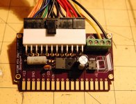
Here's what I've got so far. I had three boards fabbed by OSH Park. They look great, they're purple, and my VT100 silk screen art came out great. Can't complain.

pic1.jpgPic2.jpg

Here's the imgur album of the same pics

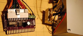
I've modified a small MiniITX power supply with an additional transformer on the outside (the same transformer on my BOM). Works perfectly, I'm getting 24 VAC on that. I've also tested the board with the ATX supply connector, and all the pads look good.

I'll be testing this in situ a little bit later. So far I'm getting good power on all the pads. Now it's just a question if I have copied the card edge slot exactly.

In case anyone is wondering about the original power supply, I also sourced the original switching transistor and replace it. No dice, but at least I have a neat objet d'art for a mantlepiece or something.
 
The results are in! They're not promising!

I plugged in my DIY power supply, turned it on, checked all the voltages going to the main board, and still... nothing. It's actually quite a bizarre problem I'm having here, and now I'm deeply into something wrong with either the main board or video display board.

I was wondering if anyone from MARCH would be making it to the NYC maker faire next month. I'd really like to get a second opinion on this, if anyone is willing.
 
You're going to have to be a bit more specific about what makes you think the problem is now on the main or video boards. I assume you believe all of your power supply voltages to be correct?

When you plug the keyboard in, do any of the LEDs light? Do you see a glow at the neck of the CRT? Do you hear anything?

Lou
 
Well after thinking about this for a while and doing some experimentations, this is what I can conclude:

* The voltages on my DIY power supply are okay. Everything is stable (there's a load on the ATX supply), and everything looks clean enough on my scope. Bit of ripple on the -23V line, but I've seen worse.

* I'm getting power to the VT100 main board. I traced the ribbon cable from the PSU to the 'front' of the board and probed the connections. Again, good power.

* Plugged in a keyboard, nothing happens. No glow at the CRT neck either (I'm guessing the glow would be fairly prominent, right?)

* I know the orientation of my DIY PSU is right. Otherwise, given how the card edge slot is laid out, I shouldn't be able to see any voltages on the board.

This is just pure speculation, but it could be that my card edge slot is just a bit off. I don't see how this is possible when I hold it up to the original DEC supply, but that's a possibility.
 
Very strange !

Does not a "hidden" signal line missing, by chance ?

My two cents : I would check, on the original P.S. that pin "H" is REALLY without any trace/wire.

I know, it's seems too simple to be true, but it may worth giving it a look.
 
The +12V supply basically goes straight to the heater on the CRT, with only a 2A fuse on the video board interposing. You should be seeing a glow at the neck of the tube. Turn off the lights in the room to look for it. If not, check the 2A fuse.

More than that has to be wrong however, because the keyboard is also powered by +12. Do you see +12 at the tip of the keyboard phone jack?

Lou
 
Last edited:
Ok, it's been a few days now, so it's dumb question time...


Something occurred to me when you originally posted that ATX 12v was making it to the motherboard, but that there were no signs of life in it, the crt or the keyboard.

So this begs the question - did you examine the return side?

That is - make sure the ground side of the motherboard components were at zero potential to the ATX ground rails for the 12v.

Another question would be "did you perform a shorts and continuities test on your raw PCB to make sure they fabricated it correctly?" (Thru plated the holes etc)
 
Last edited:
Haven't checked in here for a while, but curious about lack of success. My very crudely-made prototype worked and still works.

I would check very carefully on the ground rails. My design works with only a single 12v and a single 5v ground, but we know that the VT100 has a separate ground connector at finger J that goes to a separate secondary circuit in the original VT100 PSU which isolates the 12v ground from the 5v ground (logic ground). This must not be connected to the common ATX ground or it will stop the VT100 dead. Your original layouts look correct, but if in fact J is connected, or your VT100 or VT103 motherboard has any other variations that require a ground isolated from the common power circuit, this could be causing your problem. You should look very carefully at each finger of the original PSU edge connector to be sure if any other fingers need to be isolated from ATX ground to avoid logic grounding.

Rick
 
Last edited:
If anyone is reading this in 2023, you're welcome.
I'm a year early, but thanks. I have a VT131 with a giant dead transformer. Your git says this should work with a VT101 or VT102, but I don't see how because it looks like the 101 series (101, 102, 131) use the power supply card to pass some signals between the Video and Logic boards. Has any attacked this problem specifically for the VT101 series? If not, I think I'm about to head down that path..
 
Aren't those lines Vertical Horizontal not just pass-trough lines, just for ease and reduce extra connectors?
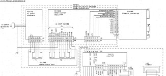
See Block Diagram I found of the VT101. SO check if indeed just a pass.

Further any kind of supply that can be used, even with this transformer (if still works)
Only extra are the safety build-in is to take extra , so if fi a +5V fail is there , or too high/Low etc.
All those you quite easy can make your own.
Just look internet for some PSU idea's and safety managements how to build them.
 

Attachments

  • VT101-Block-Dia.jpg
    VT101-Block-Dia.jpg
    246.9 KB · Views: 18
Last edited:
Aren't those lines Vertical Horizontal not just pass-trough lines, just for ease and reduce extra connectors?
See Block Diagram I found of the VT101. SO check if indeed just a pass.

Further any kind of supply that can be used, even with this transformer (if still works)
Only extra are the safety build-in is to take extra , so if fi a +5V fail is there , or too high/Low etc.
All those you quite easy can make your own.
Just look internet for some PSU idea's and safety managements how to build them.
You're right, these are just pass through, and I was able to cobble together a working solution from an ATX power supply and a Boost/Buck DC-DC converter for -23V. The 101 series will not work directly with this board because it doesn't use the card edge connector, instead uses a 12 pin header directly to the logic board and a 7 pin connector to the video board (with the PSU board doing some pass-through.) Glad to have it working again, finding this post (and the earlier post referenced within) were a big help.
 
Not to resurrect very old threads needlessly, but I had these boards made from the gerbers on Github (before noticing there was an OSHPark shared project already, oops) and neither the +12V or +5V grounds were actually connected to ATX ground. I was surprised, enough that I pulled in the Eagle files into EasyEDA, and sure enough the rats for both pads were still there waiting for their traces.

Small digression: I have a VT105, so things may be slightly different, but my understanding is it's the same as the VT100 with an additional waveform graphics card. Regarding RickNel's now vintage comment, on my original dead power supply, the +12V and +5V ground connectors are very obviously directly connected on the board with a large trace between them, they are not isolated in any way. The schematics for the PSU also show both grounds being tied together. The more likely case is my understanding of ground isolation is limited and I'm missing something. At any case, I'll be bodging in +5V GND to ATX GND first, seeing if leaving the "J" fingers floating works for bringing my terminal back to life, then going from there.

Thanks to BBenchoff for making this board. One issue of note I found, that actually doesn't affect anything, is the pitch of the traces on the card edge portion of the board are slightly off from the pins in the edge connector and the original PSU in my VT100. However, it's so slight that all the fingers touch the pins still. I'm curious if others' original PSUs' edge traces may be a slightly different pitch from my VT105.

Another added benefit of doing this a decade later is SFF ATX power supplies can be had for decent prices on Amazon and elsewhere in a stylish black paint job that you have to scrape away when you want a grounding point on the case itself.
 
Back
Top