• Please review our updated Terms and Rules here

Fixing up a Hitachi V-509 Oscilloscope

Hello, many thanks for checking... the service manual asks for a time mark generator and I don't have such a device.

I've got a function generator, Wavetek 143, which has probably never seen a service is its life and is most likely not 0.5% accurate. Is that sufficient or do I need a time mark generator and is there a difference between that and pulse generator?

I'll be on the lookout for one and I'll try to check I can get somewhere with the old Wavetek.
 
The time marker generators are handy because they produce a series of short duration pips or pulses which are dead easy to line up with the scope's CRT graticule. I use the Tektronix TG-501 plug in. But you can just as easily, for this scope, us a function generator with square waves, provided it is at least Xtal based and has a frequency counter. Or, if you just have a cheapo generator it can also do, if you have a good frequency counter to monitor it.

You need to find out why the sweep frequency is off, whether it is on all time /div ranges or just some of them, so as to figure out if something has failed or that someone has been tampering with it.
 
It would be nice having those Tek frames and modules, but they're rather expensive for what I would be using it for. I do have a frequency counter, the main reason to get it was because the dial accuracy of the FG is way off and probably the reason why it ended up in the thrift store.

I tried calibrating the scope according to the procedure 8, 9 and 12. Except for the fact that my generator doesn't go to 0.1us with asymmetric pulses, I was able to improve the accuracy of the horizontal sweep.

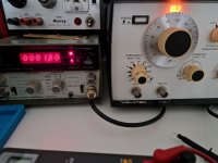
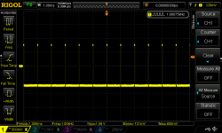
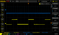
Here is the test setup:

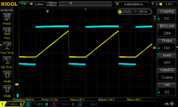
v509-h-testsetup.jpgv509-h-testsignal.png

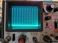
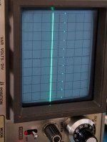
Unfortunately, there is still something wrong with the sweep or CRT circuit:

v509-h-9.jpg

The geometry is slightly off...almost like a pincushion problem?

When measuring with an input signal (scope triggered), the period is around 9ms, but the problem remains. Does your blanking pulse also look slighly off?
v509-h-10.pngv509-h-11.png
(the probe is compensated...)
 
Here is an interesting thing. The period of the wave, to end up with the correct spacing of the time pips on the CRT face, among other factors relates to the CRT's EHT voltage. The reason is that for an electrostatically deflected CRT , all other things equal, the amount of deflection of the beam is roughly inversely proportional to the EHT. So, with a higher EHT voltage, the time pips would be more crowded, requiring a longer scan period to get the markers on to the graticule accurately. In my scope the period on 0.5mS/div was 9.2 mS and in your case it is close to 9mS, and since its a linear ramp making time & distance proportional we could deduce from this that the EHT value on the final anode of your CRT is about 9/9.2 or about 97.8 % of the EHT value in my scope. So they are pretty close, but not identical.

( I think you made a mention that varying the line supply to the scope affected it, it shouldn't, perhaps check the power supply voltages are correct in case the regulation of one has failed).

The point now the scope's timebase is basically calibrated is to measure the time of the flat area and compare that to the blanking time pulse. We will compare that to the figures I posted earlier to try to deduce which of the two is the defective one. It might be the blanking pulse and relate to that Cmos IC we were discussing earlier before we got diverted onto the the flat area and ramp timing.
 
This is really tricky! As I noticed already in the picture with the sine wave: the right side of the trace is slightly skewed towards the center, better visible with the pulses:
v509-h-12.jpg

When I move the dots to the top or bottom, they move. But both periods stay at 9.00ms when I feed it a 1KHz signal at 0.5ms/Div

( I think you made a mention that varying the line supply to the scope affected it, it shouldn't, perhaps check the power supply voltages are correct in case the regulation of one has failed).

I measured the voltages again (service manual steps 1 + 3, and they're correct! Even the -1.3kV is at a steady -1.35kV and doesn't move when I change the supply voltage. None of them show significant fluctuations and I'm trying to understand how the intensity change is influenced if it's not the voltages listed in the manual.
 
That is a scan linearity error, I'll check it on mine. The ramp voltage looks fine so it must be the repose of the CRT's H deflection plates. It could happen if a def plate had moved fractionally if the scope was dropped, I have seen it before in some CRT's, but it might be within spec, I will check my scope.

Another way this could happen, which could be more likely, is the electrical drive to each plate not having the same output amplitude. They are supposed to be anti-phase copies of each other, with the same amplitude. Check the drive to each H deflection plate from the deflection amplifier outputs.This must be ruled out first before blaming the CRT.

Can you measure the exact time of the blanking pulse and flat part before the ramp. We still have not figured out which of the two have the wrong duration.
 
That is a scan linearity error, I'll check it on mine. The ramp voltage looks fine so it must be the repose of the CRT's H deflection plates. It could happen if a def plate had moved fractionally if the scope was dropped, I have seen it before in some CRT's, but it might be within spec, I will check my scope.

Another way this could happen, which could be more likely, is the electrical drive to each plate not having the same output amplitude. They are supposed to be anti-phase copies of each other, with the same amplitude. Check the drive to each H deflection plate from the deflection amplifier outputs.This must be ruled out first before blaming the CRT.
The scope's frame is slightly bent at the back, it could very well be that it was dropped. Today is a busy day, but tomorrow I probably have time to look at the H deflection amplifiers.
Can you measure the exact time of the blanking pulse and flat part before the ramp. We still have not figured out which of the two have the wrong duration.
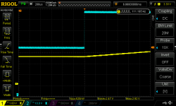
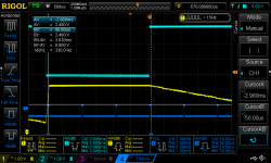
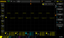
I took this measurement, including the signal from the V-509's CH 1 out fed into CH 4 of the DSO, as even the pulse width influences the figures:

v509-h-13.png
 
The scope's frame is slightly bent at the back, it could very well be that it was dropped. Today is a busy day, but tomorrow I probably have time to look at the H deflection amplifiers.

I took this measurement, including the signal from the V-509's CH 1 out fed into CH 4 of the DSO, as even the pulse width influences the figures:

View attachment 1246577
It looks, as we know, that the blanking pulse is un-blanking a tad too soon.

But what is the duration that the blanking pulse is low, and what is the duration that the flat part before the ramp is flat ? (and that currently on your scope the period is 9mS on the 0.5mS/div range timebase A).

If we scale it to relate to the measurements on my scope and figure out if it is the blanking pulse finishing too soon, or the flat part of the ramp being too long, then we would know what part of the circuit required further investigation.

Just eyeballing it from the trace it looks like the blanking is about 3.05 mS long (compared to 3.3mS on my scope) and that the flat part of the trace is similar.

Since your period is 9mS compared to my 9.2 mS. we can scale the timing up by 1.022, so your flat area is about 3.1mS and the blanking as about the same. Scaling down the blanking pulse, from my scope to match yours it is 9/9.2 x 3.33 = 3.25 mS , but your blanking pulse is only about 3.05 mS long.

The inescapable conclusion is that your flat area and ramp is ok, but your blanking pulse is terminating too soon. Back to IC 505 for investigations.
 
Thanks for checking against your scope... I'll wrap up some smaller projects to free up bench space and then I'll start disassembling and hope it doesn't require much to get to this middle board.
 
At least the leading edge of the blanking pulse looks perfect, starting just a little earlier than beam flyback. It will be interesting to figure out why it is terminating a little too soon. We will have to study the schematic to figure out exactly what factors determine its duration.
 
Ok, I finally have some time to look at the V-509 again.

There are some good news: I found another V-509 that I couldn't pass up because it was very reasonably priced... it has only a few scuffs and came with its front cover, manual and original probes even. It seems to work well too (no brightness problems here) :)

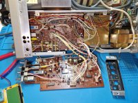
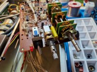
This also gave me enough confidence to dive into the faulty one and I'm trying to pick up where we left off. I have to thank Japanese engineering and the serviceability of equipment in mind of that time because the trigger board can be removed very easily (by removing the screws, side panel frame and some connectors) and then folded out:

v509-ic505-2.jpg

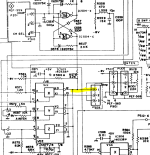
It was the IC 505, right? Unfortunately on a first glance nothing looks suspicious. I set up everything, scoped the pins and most of the time it was either +5 V (5.16-5.25 ish), -5 V, nothing at all or a pulse with a period of 9 ms in various offsets.

v509-ic505-1.png

I will look at the schematic again and now that I have access to the board in the middle it should be possible to continue troubleshooting
 
I put this back on my bench, in my quest to reduce my backlog and finish open projects. I'm going to find a replacement for IC 505, to rule it out. I hope the board is not too complicated to remove.
 
To remove the board in question, the two knobs need to be removed and unscrewed.
v509-ic505-3.jpg

I removed too many knobs and part of the frame. Some of the screws on the front bezel frame are not Philips head, but JIS and I only noticed it after stripping one of them. In the end it was unnecessary for removal of this board.

As all of it is connected via molex connectors, I might attach this board to the other scope to see if the fault follows the board
 
The fault follows the board. This also excludes the intensity pot as fault source, as I used the one from the good scope
 
Well now you have two of these scopes, and one is normal, you should be able to get to the bottom of the differences in the defective one.
 
Well now you have two of these scopes, and one is normal, you should be able to get to the bottom of the differences in the defective one.
You're right, but it is still hard because I'm not familiar with complicated analog circuits.

I found a genuine Hitachi 14053BP and replacing it didn't make a difference. I also forgot to attach some coil on the CRT (L1101) and now channel 1 has a DC offset, even on ground setting. Not sure if it is related. I must admit, it's hard to stay motivated if I'm even making it worse than before. Maybe I should give up here and pass the scope along to someone else.
 
Have you got the service manual for the oscilloscope in question and do you keep a logbook of your work?

I find the former invaluable if they can be located - do a bit of browsing. They generally indicate what the parts are and how you disassemble things.

By keeping a logbook, you note everything you do, and in the order you do it. If you perform any tests, you write down what you are doing and the outcome. When it comes to re-assembly, he logbook should identify what you have done and reassembly should be the reverse order.

The same thing applies to everything I do - keep a notebook...

If you have to leave a project, leave enough information in the notebook to restart your work again (i.e. the notebook should detail all of the work you have done previously and all of the test outcomes.

Dave
 
I do have the service manual, I don't keep a logbook... if I opened a forum thread somewhere I just come back to the thread and re-read what was done.

However, for the past projects I started taking more pictures of the disassembly process and I'm keeping the screws and other small parts in ice cube trays instead of bags. This makes reassembly less frustrating.

Since the fault is on one board, I'll try to measure it side by side and hope to find it quickly, otherwise I think it's ok to move on
 
The ZAmp deviates by ~100mV on the faulty board, where as it stays fairly close to 0.63 V when switching from A / INTEN

1724270933713.png

Since the fault follows the board I can probably eliminate the PEF-560 board (I hope). I also noticed that my 5 V supply is off on both scopes. On the good one it's around 4.8 V, and on the other one 5.2 V
 
I don't get it, this is with both horizontal sweep settings at the same position, IC 505 pins 15 + 12

bad board
DS1Z_QuickPrint33.pngDS1Z_QuickPrint34.png

good board
DS1Z_QuickPrint35.pngDS1Z_QuickPrint36.png

why does it look so different?

I think I'll quit here... it's taking away too much time from other projects and also above my capabilities
 
Back
Top