• Please review our updated Terms and Rules here

FlashFloppy-OSD on a TTL display?

bladamson

Veteran Member
Joined
Nov 11, 2018
Messages
989
Location
Appalachia
Hey folks. I figured I ought to ask here before I start experimenting and blow something up. :p

I'm looking to hook FlashFloppy's on-screen-display to various TTL video displays. The first one will be a Kaypro, but I'm also looking at doing a TRS-80 Model II and a Tandy 1000HX.

The flashfloppy-osd documentation says things about "vga" and "15khz" timings, but it doesn't have anything to say about other timings. I know MDA runs at an oddball non-15khz timing, but I don't know about the kaypro or Model 2. The 1000HX is TGA (CGA) and most certainly 15khz except for that one weird mode that nothing uses.

It looks to me like flashfloppy-osd uses the sync signals as inputs to sync its video line up to the display, and then uses its video line to pull the display up or down, right? So I hope that the exact timings aren't terribly critical, and it will sync to MDA type timings alright?

It also appears that all the hookup examples are 0.7vpp VGA or analog RGB video, rather than TTL video. I assume the bluepill is running at 3.3v, so is this going to work with 5v TTL video at all? Do I need to buffer it through a 5v device to raise the voltage? Is it going to damage the host computer's video output when trying to pull the signal low? Do I need to stick an open-collector buffer on the video output or something to isolate it?

Sorry for my dumbness. I just don't want to fry my hardware doing something stupid, heh.

Thanks, folks. I'd really appreciate any advice.
 
So to kind of answer my own question a little.....

The hookup diagram on their wiki shows a 270 ohm resistor in series with the video signal from the bluepill, hooked up to an analogRGB/VGA type display. It looks to me like that resistor in combination with the 75 ohm termination in the monitor would act as a voltage divider to reduce the bluepill's signal voltage to around 0.7v, compatible with VGA/analogRGB. It appears to just assert this signal in tandem with the system video.

When the bluepill asserts low on its video line, the 270 ohm resistor would have to pull the system video signal to ground in parallel with the 75 ohm termination in the monitor. That seems like it would be a really low resistance and more or less short out the system video signal, but I guess analog RGB signals are able to cope with that without something blowing up.

When the bluepill is not drawing its little OSD square, it must tristate its video signal. Otherwise it would pull the whole screen down while it was active, which it does not appear to do in the videos.

Trying to hook up a TTL video signal like that, however, is going to draw waaaaay more current from the system video line than it is probably designed for, though, and eventually damage it. Additionally, the 3.3v signal from the bluepill may appear very dim, depending on how the analog video circuitry is built.

I suspect that the "correct" way to hook the OSD up to a TTL video signal is to combine the system video and the bluepill's with a logic gate, and to buffer the H and V sync signals such that the gate lag is the same across all 3-4 signals (or 6 signals in the case of CGA). I suspect that a 7432 would be sufficient for this task. However, doing it this way would prevent the OSD from blacking out the system video within its little square. If indeed the bluepill is tristating itself when outside of the OSD square, it ought to be possible to modify the firmware to assert some kind of "active" pin instead, which we could use to gate the OSD video signal to the monitor and suppress the system video, which would make it correctly black out the system video in the OSD area.

Does this make any kind of sense, or am I pulling a Dunning-Kruger move here? What percentage full of poo am I with this?

Thanks again.
 
I figured the system video would be delayed too. But maybe it isn't enough to matter, depending on the logic family used.

I got a reply from the creator-dude on github saying:
What you suggest makes sense. In fact OSD already has a configurable output mode where the single Tri-state output pin is changed into a pair of push-pull pins: output and output enable. This is to allow the kind of buffering you discuss.
 
I figured the system video would be delayed too. But maybe it isn't enough to matter, depending on the logic family used.

We're talking worst case a dozen nanoseconds or so for any reasonable logic family, so I don't see the harm in having a buffer. (A single CGA pixel is about 70 ns wide.)


I got a reply from the creator-dude on github saying:

I was going to mention that it looked like they already did that in a reply last night, but sleep-brain claimed me before I could get to it. See "Display Enable" here.

Since when you're holding a hammer everything looks like a nail my suggestion for a buffer on TTL (CGA or otherwise) would be to program a GAL16v8 to do the buffer job. Run the video signals (RGBI or just video/intensity for TTL monochrome) to input pins on the GAL along with the outputs from the Flashfloppy OSD. (I assume the "output enable" is active for the whole "box" area and the "output" line will be high for the actual letters.) Program the GAL so a set of output pins will either pass through the video inputs unmodified or set the outputs to display the OSD pixel information when the OSD buffer enable is active. Since you can program the output equation for the enable state to whatever you want you this setup will let choose whatever foreground/background colors you want. (And they'll be consistent; with the "additive" mode this thing uses by default on analog displays the color of the OSD is going to be affected by whatever's underneath it. I imagine it gets really washed out when you have a high-intensity background the same color as your chose to tie to the output.)

There's no need to run the sync signals through the GAL, but if you're worried about that few nanoseconds of gate delay for the pixels relative to the sync you *could* run the sync signals through it too. But, really, it's not going to care.

As for it working on MDA frequency monitors... that's an interesting question. *If* it's just counting some number of hsyncs past the vsync and it's able to "see" the pulses correctly, and doesn't actually count *every* HSYNC or otherwise care how "tall" the screen is then... maybe it'll "just work"? The pixel clock of MDA is a bit higher than CGA but the line rates for the two systems are pretty close so as long as the OSD display isn't too long... ?

As an aside, gotta say that the "additive" mode it uses on analog displays... realistically I doubt having the output partially pulled down by that 200-something ohm resistor is going to hurt most any DAC, but, yeah, it kinda feels wrong. And it definitely would be a bad idea to try to do that to a TTL output. ;)
 
Hmmm yeah I reckon I could do it with a GAL. Although I was kind of hoping to cobble together something that didn't require any special programmers and stuff. Although I suppose if someone is putting together their own flashfloppy-osd gotek then they probably at least have an FDTI dongle already anyway so I guess a TL866 isn't much of a stretch past that.... Hmmmm.
 
Hmmm, I think the whole thing can be done with a single LS157. Propagation delay of 9ns worst case. That should be fast enough to not have to buffer the sync lines I would think, surely. Being a quad-type device, it has enough lines for RGBI on cga, so the OSD can be made full bright white instead of a dim primary color. For MDA or TRS-80/Kaypro video we'd just only use 2 or 1 of those lines instead.

I guess for machines without internal monitors, one could get one of those ISA brackets with 2x DE-9 cutouts in it, and feed the video back into the machine to the gotek with a loop cable, and then back out to the other connector to the monitor, to make things neat. Although I suspect one would want to keep the cabling as short as possible.

Hmmmmm....
 
Hmmm, I think the whole thing can be done with a single LS157. Propagation delay of 9ns worst case. That should be fast enough to not have to buffer the sync lines I would think, surely. Being a quad-type device, it has enough lines for RGBI on cga, so the OSD can be made full bright white instead of a dim primary color. For MDA or TRS-80/Kaypro video we'd just only use 2 or 1 of those lines instead.

Yeah, a plain 2-1 multiplexer will work "fine", you can just tie any unused inputs on the OSD side to whatever you want the base color to be for your box and connect the output to drive the "active" color. If you tied all four lines to the OSD output then you should switch between a black background and bright white; if you wanted to be "clever" you could, say, tie blue or green high instead of low and drive the remaining lines with the output to give you bright white on navy blue, which would look a lot like a commercial TV OSD.

I just like the GAL idea because I have a drawer full of the things, and since you'll have some unused inputs it'd be easy to add stupid touches like switch selectable configuration for color/mono, alternate color schemes, etc. ;)
 
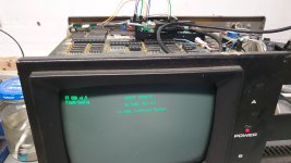
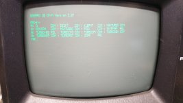
Well it was working for a little while, but then I did something dumb and fried the i2c interface on the gotek. Lol.

Now I am making a new one that doesn't suck as bad.

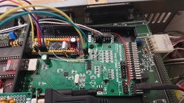
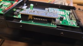
If I get some pcbs made, would anyone want one? If I lay one out, it will be something that stacks on the bluepill like in the last pic. So it could be set up externally in a plastic box dongle thing for MDA and CGA displays, and supplied with power and i2c from the gotek with a longer cable. Somebody else would have to design a box for it though.

Note the contraption that sits on the video header in the upper left to steal the sync and video signals and feed them back into the CRT. I suspect that if I laid the board out right, the contraption in the last photo (that's the new one that doesn't suck as bad) could just plug into that header as a unit and get power and i2c from a longer cable from the gotek as above, too.
20221019_114900.jpg20221019_115728.jpg20221019_152010.jpg20221019_233953.jpg
 
As much as I've used the Blue Pill MCUs, the STM32F4 "Black Pills" are at the same price point (via AliExpress, ~$2 each), so I've gone to those. The F4 MCU is quite a bit more capable with nearly all GPIOs rated for 5V. I probably will use my stash of Blue Pills up and not re-order them. The Black Pills are either STM32F401 or 411 MCUs--more memory and flash and a faster core--and hardware floating point.

FWIW.
 
Back
Top