• Please review our updated Terms and Rules here

"Fun with BIOS" Programming Thread

The idea of this was to figure out what boot-only games were doing their boot process. There were quite a few that employed encryption while booting.

It was not a general DOS utility. Just something whipped up in an afternoon to answer a question or two. It did its job.
 
There is no destination, and none is required. The value read from 0x00000-0x0FFFF is just placed on the bus, and every device just ignores it - it's just the reading from RAM that's required, the value doesn't actually have to go anywhere.

What does all this mean for a BIOS author? It just means that you need to set PIT channel 1 to binary mode 2 with a count of 18 cycles, set DMA channel 0 to auto-init, read, single, increment with an address of 0 and a count of 0xFFFF and everything should just work.

I've written more about DRAM refresh on 5150/5160 machines on my blog: http://www.reenigne.org/blog/how-to-get-away-with-disabling-dram-refresh/ .

I appreciate the hint on how to program the DMA controller to make my life easier as a supplement to the 8237 datasheet. However, what you're saying about "no destination is required" bothers me, 2 months later :p!

What is the guarantee in either the IBM PC circuitry or expansion cards (BESIDES memory cards of course) that they will all ignore the value on the bus while Channel 0 alone is active? I am aware that the ISA bus has an DMA AEN (Address ENable) pin which is often input into a gate along with the address lines to determine whether to 'clock' a data value into the 74HC373 octal latch or equivalent... if DMA is enabled, an AND gate with the decoded address and AEN will cause the latch to not receive a clock signal to accept new data, so expansion cards can thereby ignore values. That's my educated guess on how cards know to ignore DMA.

But what about if Channel 1 through 3 is active, to perform a floppy disk transfer, for instance? I'm guessing there are extra logic/gates to determine whether the correct channel (DACK1-3) AND AEN are enabled?

As for mem-to-mem, I remember reading that on the IBM PC, mem-to-mem DMA cannot be performed, so that mode of the 8237 is not used. What eludes me is why it cannot be done (i.e. what hardware is missing or prevents it). That being said, isn't it theoretically possible for a memory chip to inadvertently accept the value (i.e. CAS is asserted) on the bus during RAM refresh?
 
What is the guarantee in either the IBM PC circuitry or expansion cards (BESIDES memory cards of course) that they will all ignore the value on the bus while Channel 0 alone is active? I am aware that the ISA bus has an DMA AEN (Address ENable) pin which is often input into a gate along with the address lines to determine whether to 'clock' a data value into the 74HC373 octal latch or equivalent... if DMA is enabled, an AND gate with the decoded address and AEN will cause the latch to not receive a clock signal to accept new data, so expansion cards can thereby ignore values. That's my educated guess on how cards know to ignore DMA.

But what about if Channel 1 through 3 is active, to perform a floppy disk transfer, for instance? I'm guessing there are extra logic/gates to determine whether the correct channel (DACK1-3) AND AEN are enabled?

Yes, exactly - a DMA device has to know both that a DMA is in progress and that it's on the correct channel for it not to be ignored. There's no -DACK0 on the ISA bus so all ISA devices will ignore channel 0 DMA.

As for mem-to-mem, I remember reading that on the IBM PC, mem-to-mem DMA cannot be performed, so that mode of the 8237 is not used. What eludes me is why it cannot be done (i.e. what hardware is missing or prevents it).

The 8237 is a 16-bit device so you need a separate 4-bit page register for each channel to determine which of the 64KB pages in the 1MB address space is being read or written (that's the reason that DMA transfers cannot cross a 64KB page boundary).

The 8237 can do memory-to-memory copy from channel 0 to channel 1. Unfortunately in the PC architecture these two channels share the same page register. So you can do memory-to-memory DMA but only from part of one 64KB page to somewhere else on the same 64KB page - not terribly useful! It's too bad the IBM designers didn't think of this and arrange for these two channels to have different page registers - it would almost certainly have been a trivial change to the hardware and would have been extremely useful!

That being said, isn't it theoretically possible for a memory chip to inadvertently accept the value (i.e. CAS is asserted) on the bus during RAM refresh?

To the memory the RAM refresh is just another RAM read, so CAS will be asserted at the appropriate time. However, it's a memory read operation rather than a memory write operation, so (assuming the hardware is all working correctly) no memory contents will be changed.
 
Yes, exactly - a DMA device has to know both that a DMA is in progress and that it's on the correct channel for it not to be ignored. There's no -DACK0 on the ISA bus so all ISA devices will ignore channel 0 DMA.

Actually I forgot that DACK0 isn't on the bus... that being said, memory expansion cards- or any memory-mapped I/O cards for that matter- would just ignore AEN altogether for reads, correct? Although sergey has said to me before that reads to I/O ports can change their state (so the state of AEN is significant), I don't know if that applies to memory-mapped I/O. I really should just make a simple toy ISA card for this lol! I have ISA protoboards lying around.

Thank you for the clarification. I brought up DMA for a reason- I'm carefully considering whether to make the debugger bare-metal capable instead of having it rely on the existence of BIOS functions. This means that I will have to at a minimum detect the top of memory, set up PIT channel 1, DMA channel 0, give a serial port some default parameters, and initialize the CRT controller. But it would potentially make the debugger far more useful- and I have to implement those functions anyway before passing control to the debugger while I test my BIOS on real hardware ;).
 
Actually I forgot that DACK0 isn't on the bus... that being said, memory expansion cards- or any memory-mapped I/O cards for that matter- would just ignore AEN altogether for reads, correct?

Yes, exactly - the memory side doesn't care if it's a DMA or not, as far as it is concerned it's just a read.

Although sergey has said to me before that reads to I/O ports can change their state (so the state of AEN is significant), I don't know if that applies to memory-mapped I/O.

No reason why it couldn't. Obviously in that case you'd have to monitor AEN or just be careful not to DMA to/from the memory-mapped IO addresses if you don't want those state changes. If your memory mapped device is mapped above 64KB (as it almost certainly would be) you don't need to monitor AEN just to avoid the refresh DMA transfers, though - you can just do your normal address decoding as refresh DMAs will always be in the first 64KB of address space.
 
The 8237 can do memory-to-memory copy from channel 0 to channel 1. Unfortunately in the PC architecture these two channels share the same page register. So you can do memory-to-memory DMA but only from part of one 64KB page to somewhere else on the same 64KB page - not terribly useful!

Oh hell -- that's probably what's wrong with my old test code. I was definitely trying to transfer between pages.

Unfortunately this new info kills the desire to go back and try it again; it is nearly useless to do a mem-to-mem DMA within the same 64K page (on 808x architecture, anyway).
 
I think that anyone who ever considered the idea of an EMS simulator or being able to copy from memory above 1M to memory below has run into that issue. I even considered a small 16-bit ISA card that would enable memory-to-memory DMA via the PC-AT DMA channels. But that's hardly a software-only solution--and what with LOADALL, it's largely ireelevant.
 
Chuck, this is a question for you...

Given a MASM struct for a small linked list:
Code:
node_w struct
	value dw ?
	next dw ?
node_w ends

And a near pointer to the first node of this list, how would I traverse the list in MASM? It is to my understand that to reference members of a struct, you need to create a named variable for it. But what if I just want to dereference the pointer in a register and have MASM add an appropriate constant offset to the struct?

Example of what I'm trying to do:
Code:
mov bx, [bx].next ;Get the pointer to the next link in the list
would resolve to:
Code:
mov bx, [bx + 0x02] ;Get the pointer to the next link in the list

To further complicate things, I have three types of structs for this list- node_b, node_w, and node_d, where the value is a different size in each. The list can consist of any combination of these nodes, but each command of the debugger knows the order it expects. Is there a way to "typecast" each node so the appropriate offset is generated by MASM as each linked is traversed (obviously this isn't in a loop)?
 
Which version of MASM? The treatment of structs by MASM changed somewhere around 5. At some point, member items in a struct became local to the struct name, so, in your example, you'd have to address it as [bx].node_w.next. You can create a UNION of your different structures and then address each element as .union.struct.element.

I hope this answers your question...

I'm using WASM, which is between 5.0 and 6.0 in compatibility... though I'm going for 5.0 compatibility. I'll try that when I get the chance.


I'm still alive :p, though I haven't made much progress this month. Short version is that I spread myself too thin working on my thesis research and multiple projects- also someone who I contacted months ago regarding helping him with his own project suddenly got back to me, and by impulse I got interested in helping him out. Additionally, while my code doesn't need to be rewritten, my project tree needs to be redone from scratch.

For those who have been taking interest in this thread- please know that this is a long-term project for me (I know writing a BIOS/debugger is nontrivial), and there are times I will need to break or will not have as significant amount of activity compared to other time frames. I thank each and every one of you for your advice, feedback, and interest.
 
Yes, I'm working on this again.

BIOS does not lend itself well to modularity- trying to divide segments/class into multiple source files has been a task in and of itself. I've basically come to the same conclusion that John Foster did in his BIOSkit book- trying to divide a BIOS into multiple source files cannot be done with the assembler/compiler alone. MASM just doesn't give you enough freedom by itself to calculate the distance between two segments in separate translation units.

So right now, I have essentially two options: Limit all compilation to using the WATCOM assembler and linker, which can position code segments absolutely, or create a C utility that takes in a fully-linked BIOS with a header that tells where code should begin and end, and checks to see if all code sections are in bounds- essentially, a custom linker. Neither option sounds exceptionally appealing- I still would like the code to be compatible with most MASM assemblers (I can generate BAT files from SCons for other assemblers), just in case. Anyone have any other suggestions?

Regarding most of my previous troubles with the assembler and linker- I figured out a build system to allow me to add and remove modules at will in the BIOS while still enforcing IBM-compatible entry points... simply make judicious use of the class directive! This way, I can worry less about the actual order of object files on the command line; the linker will normally concatenate segments in order of the command line, but the CLASS of each module's segment overrides the command line order. Provided that I can solve the above problem with absolutely positioning segments, I think I have otherwise found a solution where I can add and remove code without having to alter the order of compilarion each time.
 
I've only just now found this interesting thread. I'll need to catch-up and reread it from the beginning thoroughly.

Here's what I can contribute from my read so far...

Last time I did a BIOS was the late 1990's. At that time, I elected to use a DataLight ROM Dos in an embedded 386EX design. Their ROM DOS included a royalty free BIOS - distributed in source as part of the package. (I heard this BIOS eventually went OpenSource) Ultimately I didn't need to use DOS at all - and the BIOS was needed only to get an initial config.sys and program into memory. My application patched all the interrupts it needed to it's own routines and dealt with FLASH ROM files naively with it's own code.

In my particular application - there were a lot of build and compile options - in fact, a totally open field as there was no previous code example for my CPU and the hardware environment was totally unique (my own design from scratch) The project ended up only needing Real Mode though I had planned a Protected Mode path in case it was ever required.

I ended up with two builds. The first, loaded a BIOS from ROM into RAM - and executed it there along with my Turbo386 Debugger Driver. From there, my application code was downloaded via serial link to the target system RAM where both it and the BIOS could be debugged using TD-Remote and Turbo-C.

The second build, intended for customer delivery - ran the BIOS from ROM and only the Application was run in RAM - copied there from another ROM.

Borland's Turbo-Assembler was able to compile the BIOS as needed, though I had to customize it to setup the chip-selects in the CPU part, to remove code for items like video hardware - which were not present in my system - and substitute a serial console session to COM1.

BIOS modifications were done in Assembly, although my Application used C with embedded Assembly directives in a few places. A quirk of mixed Assembly and C arose because of the math package used in the C compiler. This was dealt with by a stack copy in some systems - though mine didn't require it. Knowing about this issue was the limitation that prevented many C environments from working well on such systems.

I'm not sure how much of this thinking would be helpful to you. If you have specific questions I'll try to recall the work and answer them.

Great thread BTW.
 
Thanks for the compliments and feedback.

I know this thread is rather long, but the major gist of it beyond me asking questions about BIOS or MASM is this:

I want to build a modular BIOS where a user inputs a config file and the build system takes care of either building the correct set of object files OR generates the correct set of commands to build the BIOS, if the user wishes to build and test directly on DOS. My build system of choice is SCons, which requires a modern version of Python. I can coerce it to generate a list of commands to run on a modern machine which can be piped to a batch file and run on the target machine. Perhaps in the future an NMAKE-compatible Makefile is possible as well.

Because I wanted the source to be modular with features (example- try to support/don't support over 640k, boot both floppies/only one, add XT extensions to a PC motherboard/stay true to the PC motherboard BIOS features, turbo/no turbo), I need a way to insert remove code at will. Such a setup is NOT conducive to a single source file that has possibly hundreds of ".ifdef" or "#ifdef" conditional compilation blocks, and the boundaries between where code from one module ends and a number of other modules to add next won't always match up (though I can always enforce a convention for this between modules- i.e. if Module A connects to Module B, certain assumptions about CPU state/the PC state must be made).

My original goal to build it in C, while possible (there is a proof of concept zip file somewhere in this mess of bare-metal C that boots and beeps the PC speaker), felt impractical, as short of a #pragma hack it was impossible to suppress saving all registers in the interrupts and wasting space.

So to that end, I decided to write it in MASM/WASM assembly and use multiple source files divided by purpose, using the SCons build script to choose or exclude certain files in order (key here) depending on the user's preferences in a config file. This setup would work fine if it wasn't for me learning that IBM and most clone BIOSes have a number (about 30 or so) of data structures and entry points (mostly interrupts, but other code as well) at literally the same address for compatibility with the PC motherboard. It appears no one listened to IBM when they said "don't directly jump into BIOS directly- entry points may change at any time".

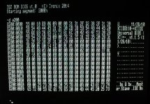
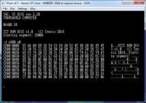
So for compatibility, any BIOS I create needs to make sure that each hardcoded data structure is a module, and that modules with "freely movable" code do not overwrite modules with hardcoded entry points due to being too large. The Generic XT BIOS solved this problem by using a single source file with a single logical MASM segment, and a macro that calculates the empty space between the current address (after the preceding code is done of course :p) and the start address of the next absolutely-positioned code. This macro then pads the empty space with 0xFF.

This does NOT work when multiple source files are used- although the GROUP directive treats logical segments as one large segment, all references to the current assembler address are relative to the current logical segment, instead of the beginning of the group... so if a new segment belong to a specific group starts at 0x300, '$' will point to 0, not 0x300. This makes all calculations to figure out the number of bytes to pad incorrect. From what I have gathered, it is impossible to get the distance between two different segments in MASM alone. As each segment in different modules has a different name, I haven't tried the public "combine" type yet to see if the same thing happens.

With that solution pretty much shot, the other solution is to specifically require a linker which can position OMF object file segments absolutely. The only such linker I know that can do this is WLINK. But the linker command lines to do this are complicated, and just having this responsibility alone also prevents me from easily adding or removing functionality, since the linker command line, build scripts, and ordering must be changed accordingly when functionality is added or removed. Small changes become more difficult/tedious to test on real hardware.

Additionally, the hardcoded entry points may also complicate the order in which object files must be linked, since order now matters beyond just making sure the hardcoded 8088 jump is last and the jump to 0xF000:0xE05B is first. This is partially alleviated using MASM classes- each source module contains either 1 or a few segments using MASM classes that control the order that segments are loaded. This makes sure thas long as modules of a particular class are linked in the correct order, I need not worry about the exact ordering of modules. Any "extra features" modules are simply linked in last, and the assembler/linker makes sure they are placed next to the corresponding MASM class.

So right now, my problem of adding/removing functionality at will is partially solved, but preserving entry points, I'm a bit between a rock and a hard place deciding what to try next. Either forget the entry point compatibility, use a complicated linker setup, or use only a single source file that will become unwieldy to maintain. None of these options are appealing, though the last one may be the path I have to take- maybe I can figure out how to make a single source file easier to maintain with the ".include" directive.
 
Last edited:
You're very far along with your project - having collected and analyzed code and structure you're wrestling with the compile-time and link-time issues of the imposed architecture. (That about right?) From the sound of your predicament - you must be considering writing your own linker. It would solve so many issues for you - it seems the logical next step.

Even if you give up entry point compatibility for simplicities sake, you could put it back in later.

Your need to "size" blocks of code associated with various BIOS elements would be facilitated by a two-pass linker nicely. Syntax being of your own making - could be convenient to your precise need.

Oh well, that's the way it looks from the outside anyway. I'll go back and read for detail before posting again.

Thanks for the catch-up. Your project is something I've often thought of doing myself - but you're having much more fun!

With all due respect, the thought of me writing a linker makes me want to vomit... I'm not exactly sure I'm qualified to write one either XD. Additionally, that wouldn't solve the problem of having to update linker command lines (with segment names and offsets) each time functionality is added/removed. Or am I missing the point?

It might be beneficial to give up compatibility for now. I don't actually KNOW persay, how important entry-point compatibility is when running programs in the real world. I just know that most BIOSes did it (the COMPAQ Portable I being somewhat of an exception... not all entry points and table locations are the same), and a book on BIOS development had a table of compatible offsets.

EDIT: Spoiler Alert- there's nothing in this thread resembling a complete BIOS/debugger thus far. :p Mainly proof-of-concept EXEs.
 
Last edited:
Screw it... I started over with a single source file. I was able to concatenate nearly all the work I did trying to divide source files into modules over the past 6 months (on and off, obviously :p) in two hours.

I have attached a template of sorts. It does look similar to the Generic XT BIOS for now, but it'll deviate (example- Generic XT BIOS attempts to use the stack before checking that the first 16kB is OK). I already made a git repo, but I haven't pushed it- I want to make a working binary before that... the bare minimum anyway.

On that note, I need to look up the minimum interrupts which need to be implemented by the PC to run DOS.
 

Attachments

  • PCBIOS.zip
    4.9 KB · Views: 1
This setup would work fine if it wasn't for me learning that IBM and most clone BIOSes have a number (about 30 or so) of data structures and entry points (mostly interrupts, but other code as well) at literally the same address for compatibility with the PC motherboard. It appears no one listened to IBM when they said "don't directly jump into BIOS directly- entry points may change at any time".

So I've just started writing a BIOS for my new 386/486 ATX board. I'm a little bothered by the above statement. My assumption was these programs were far and few between and were mostly early PC programs. I elected to drop offset compatibility very early as my initial boot loader is restricted to about 4K of ROM. From there the rest gets loaded from a SPI flash or over a serial port. Does anyone know how big of a hole I'm digging for myself in incompatibilities?
 
So I've just started writing a BIOS for my new 386/486 ATX board. I'm a little bothered by the above statement. My assumption was these programs were far and few between and were mostly early PC programs. I elected to drop offset compatibility very early as my initial boot loader is restricted to about 4K of ROM. From there the rest gets loaded from a SPI flash or over a serial port. Does anyone know how big of a hole I'm digging for myself in incompatibilities?

Warning: Yet another long post follows.

I do not know for certain how problematic the compatibilities are in practice... I just know the following from my own "research" into various BIOSes and tests I ran back in August 2013. Needless to say, there's conflicting information:

  • When IBM started using the entire 0xF000 segment for ROM, they made sure that the BIOS entry points from the 8kB ROM BIOS jumped to the new routines.
  • Most clones keep their data structures, including the serial port table, the floppy parameters table, CRT parameters table, the initial IVT table that would be loaded to 0x0000:0x0000, and a dummy IRET for unimplemented ISRs at the same offsets.
  • The initial IVT table of most clones are NOT identical, but there are definitely entries which are shared, especially the dummy return at 0xFE53.
  • Notably, the COMPAQ Portable BIOS (the first compatible-clone) does NOT keep it's data structures in the same place as other BIOSes, as well as some interrupts. At least part of this was likely motivated for legal protection from IBM suing their asses. However, some initial IVT table entries (and by extension, ISRs) DO point to the same offsets.
  • A book written by Phoenix Technologies about BIOS design in 1988 or so has a list compiled of IBM-compatible entry points. Initially, this made me think "it must be important if it was written in that book", but another part of me thinks it might've just been a result from Phoenix's reverse engineering.
  • Most of the clones I tested were derived from the ERSO project in Taiwan... as Chuck(G) has mentioned before, all those ERSO BIOSes more or less derived from one original source. IBM sued ERSO for making their BIOS "too similar": http://www.taiwantoday.tw/ct.asp?xItem=119839&CtNode=103.
  • As far as I'm aware, John Foster's BIOSkit (Annabooks) does not have compatibility except for two places- the IBM signature in the copyright string starting at 0xE000, and the IVT table at 0xFEF3 and possibly the dummy ISR (?).

I do not know for sure whether the offset compatibility is important in practice, or it just became a matter of course as more people reverse engineered the BIOS and more information became available. My guess is that it's actually a combination- though COMPAQ's BIOS is significantly different (and more convoluted, IMO) from IBM's, some entry points to ISRs were kept the same anyway (I'll compile a list after I've slept a bit lol).

Lastly, if I did sacrifice compatible entry points, deployed this BIOS, and found a crashing program, I could simply check (hex code search) to eliminate incompatible entry points as a cause. If it comes to this in the quest of making a modular BIOS, then so be it. I just want to code something usable for now, damnit XD!

It appears no one listened to IBM when they said "don't directly jump into BIOS directly- entry points may change at any time".
This was at least a little bit tongue-in-cheek, referencing the fact that people would ignore IBM's recommendation and bypass the BIOS to directly access hardware for the sake of performance. Also a reference to everybody except IBM not using MCA. If IBM said/did one thing, the clones/competing hardware manufacturers did something else.

I just find it a bit curious that IBM said:
IBM PC BIOS Listing said:
;----------------------------------------------------------
; THE BIOS ROUTINES ARE MEANT TO BE ACCESSED THROUGH :
; SOFTWARE INTERRUPTS ONLY. ANY ADDRESSES PRESENT IN :
; THE LISTINGS ARE INCLUDED ONLY FOR COMPLETENESS, :
; NOT FOR REFERENCE. APPLICATIONS WHICH REFERENCE :
; ABSOLUTE ADDRESSES WITHIN THE CODE SEGMENT :
; VIOLATE THE STRUCTUR AN DESIGN OF BIOS. :
;----------------------------------------------------------
And yet to my knowledge, kept jumps to the new entry points at the old entry points anyway... maybe it was convenient for code reuse and testing code at the old locations before moving them when developing the 64kB XT BIOS and the subsequent AT BIOS? modem7, have any theories on this?

I have attached a list of notable offsets within the BIOS. In addition to other notable addresses for my reference, it includes most- if not all- of the IBM-compatible entry points mentioned in the Phoenix BIOS book.

I have a Compaq Portable I- if people can tell me some early PC software which broke on it, I could check if it called BIOS routines directly. Curiously, DOS 3.3 chkdsk is one such program that breaks on the Portable I.
 

Attachments

  • BIOS_compare.txt
    1.7 KB · Views: 1
Last edited:
Hi all,
Some days ago i write small test option-ROM (2Kb) for showing starting segment. Also support debug.exe command - D (dump). Syntax:
D [segment]{:eek:ffset} {bytes to dump}
By default, offset = 0x0h and bytes to dump = 0x100h
So, this ROM can be burn into ISA card with EEPROM socket (for example, network card), and may help with debugging self-made controllers with addition ROM. If your EEPROM is 8Kb test rom can be merge by command:
Code:
copy /b seg_tst.bin + seg_tst.bin + seg_tst.bin + seg_tst.bin test8k.bin

Assembler source code included in archive.
 

Attachments

  • P1110866_измен.размер.jpg
    P1110866_измен.размер.jpg
    96.4 KB · Views: 1
  • seg_tst.zip
    4 KB · Views: 1
  • 6f6c06021f824782a978014a1ed727e7.jpg
    6f6c06021f824782a978014a1ed727e7.jpg
    25.7 KB · Views: 1
Excuse me if this subject has been discussed before on this deep thread, but, have you taken a look at the Award Bios 1999 source code ?
 
Back
Top