• Please review our updated Terms and Rules here

H758-a Schematic

BitWiz

Experienced Member
Joined
Sep 7, 2021
Messages
420
Location
Glen Ellyn, Iil
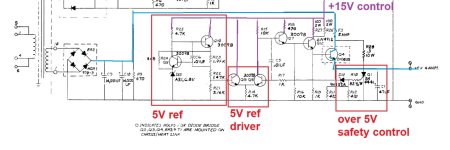
I have just acquired a DEC H758-a power supply.

The plus and minus 15VDC supplies seem to be fine but the +5VDC supply is not working (0.2VDC).

Does anyone have a schematic of this supply? I couldn't find it with a google search.

Also, what is the best way to clean it. The inside is filthy. Can I take out the PCB and clean it with 99% Alcohol without worrying about damaging any components?

My eventual goal is to use this to power my TU56 when I get it reassembled and running.

Thank you,

Mike
 
The +15 and -15 work but their power transistors get hot. The +5 does not work but I do see +10 output from the bridge rectifier.

Any suggestions?
 
The +15 and -15 work but their power transistors get hot. The +5 does not work but I do see +10 output from the bridge rectifier.

Any suggestions?

If you want to learn how this power supply works, you could model the whole thing with LTSpice. It would give you a really good understanding of the regulation circuitry.

Since all three pass transistors (Q2, Q3, Q4) are on the same heat sink you really can't tell which one is generating the heat. The +/- 15 outputs are OK, Q2 & Q3 are not generating heat. My guess is that Q4 is shorted or the Crowbar circuit has tripped, and is Q4 generating the heat.

Check the 5A fuse F3? Did someone replace it with a fuse bigger than 5A because it blew?

The SCR Q1 is a Crowbar that will short the +5V output to ground if it rises above a set limit, maybe about 6V. If the Crowbar trips it should blow fuse F3. If it does not blow fuse F3, the pass transistor Q4 will get turned on full trying to make 5V on the output. Q4 can handle more than 100W so it can generate heat like an big incandescent light bulb.

Q7-12 are all part of the voltage sense and drive circuitry for the pass transistor Q4. The Zener diode D13 is the voltage reference for the output, and Q9-Q11 are part of that circuit. Q8 compares the output voltage to the reference voltage, and controls Q7, Q12, and Q4 to regulate the output voltage. All of the reference and control circuitry is pulled up by the +15V supply, so it is good that that supply is working.

Measuring the Emitter, Base, and Collector voltages on Q4 would be helpful for debugging.
Thank you for your detailed circuit description. Once I clean the circuit board I will take some measurements and update this thread.
 
Any good suggestions on how to start with LTSpice? Never used it, but it sounds like it might help me understand power supplies maybe just a bit better. TIA.
 
Any good suggestions on how to start with LTSpice? Never used it, but it sounds like it might help me understand power supplies maybe just a bit better. TIA.
You can get it here now ... https://www.analog.com/en/design-center/design-tools-and-calculators/ltspice-simulator.html
as LinearTech was subsumed into AnalogDevices a while back.

Here is a simple tutorial video they have: https://www.analog.com/en/education...-series/ltspice-getting-started-tutorial.html

Attached are a simple LM555 example, and a 170V Nixie switching power supply based on the LM555. Just double click the .asc files to run in LTspice once installed.
Here is the simple LM555 astable example. The schematic drawing functionality is pretty easy to learn.

Capture.PNG
 

Attachments

  • LT555_examples.zip
    2.8 KB · Views: 2
Last edited:
When I fixed the +5V supply in my PDP-8/e I modelled the circuitry in LTSpice. The LTSpice model, part libraries, and schematics are attached. I have modelled other DEC power supplies in LTSpice, but the part libraries have changed so they don't work any more. I will fix them and post them.
 

Attachments

  • H724 Power Supply.zip
    4.6 MB · Views: 7
Here are the models for two different versions of the H740 +5, +15, -15 power supply that is used in lots of different DEC equipment. This one was really challenging to get working and surprising to see just how it works.
 

Attachments

  • RICM_H740-LTspice.zip
    51.9 KB · Views: 4
Now if I could just find one for the Rainbow or Decmate II PSU. But thank you for those two attachments. It gives me something to start at learning this.
 
In essence you can see the blocks of that 5V regulator.
There is a 5V control circuit and becomes its power from the +15V rail.
Start with the 5V reference voltage constructed around zener D13.
Then you have the eventually +5V power circuit around Q7 and Q12 who both drive the Power transistor Q4.

There is a safety circuit. It measures the over voltage of +5V.
When in event of over voltage, +5,6V, the Thyristor Q1 is triggered and shorts the +5V output.
Normally that fuse F3 5A should blow.

To test the PSU, remove outputs from the computer.
Just now the PSU.
Remove R28 (0.3 Ohms 10W)
Remove fuse F3.
Check Q1 Thy for shortage
Check C9 and C10 for leakage
Check Q4
Start up PSU and start with 5V ref circuit
And see if there is voltage across R13
Zener D12 1N752A is a 5,6V zener diode.

Put in F3 and measure output.
See if output is high or low.
 

Attachments

  • DH11-TU60-5V-PSU.jpg
    DH11-TU60-5V-PSU.jpg
    152 KB · Views: 7
Back
Top