• Please review our updated Terms and Rules here

Heathkit H11A Gett'er Working Thread.

Well, here's the latest round of mistakes I'll see right after posting. Lol.

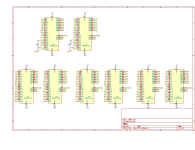
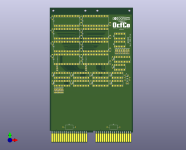
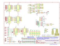
Added that "inhibit memory below the configured base address (within the lower 512k)" thing with the comparator, and rearranged some pins to make the board layout less messy.

output1.pngoutput2.png
The layout is rather fiddly, but it's getting there.....
OCFCO_QRAM.png
 
I thought that having long PC traces between the backplane connector and the transceivers was a bad idea. Would it be electrically better if you slid all of the ICs close to the finger edge connectors?
 
I thought that having long PC traces between the backplane connector and the transceivers was a bad idea. Would it be electrically better if you slid all of the ICs close to the finger edge connectors?
Absolutely true. All the bus interface ICs should be near the edge connector fingers to minimize the bus stub lengths.
 
I thought that having long PC traces between the backplane connector and the transceivers was a bad idea. Would it be electrically better if you slid all of the ICs close to the finger edge connectors?
I'm gonna move it down once I get the IC interconnections laid out, before I connect it to the bus (and maybe shorten the card, too, although the price difference will be like $4 or something iirc and the full height one would be easier to get in and out of the backplane). Just wanted to leave some wiggle room for now.

Might try to put a prototyping area at the top if it doesn't add to the board cost. I dunno. Or some blinkenlights off the data bus and address latches.
 
Hello,

Maybe I missed it in my scan through these posts, but why are you not using the open-collector version of the 74LS640 (the 74LS642)? The DC005 transceiver that seems to be the standard interface component in DEC designs has open collector outputs... just wondering.

Cheers, Jon.
 
Hello,

Maybe I missed it in my scan through these posts, but why are you not using the open-collector version of the 74LS640 (the 74LS642)? The DC005 transceiver that seems to be the standard interface component in DEC designs has open collector outputs... just wondering.

Cheers, Jon.

Because I am dumb and don't know what I am doing, heh. Thanks for catching that.

Been busy the past couple of days and haven't had any time to play with any of this stuff. :( I am hoping to throw together a thing to generate the power-up signals on my spare DEC backplane (it will be handier on the bench than the H11), get the qbone tested, and start testing cards before the end of the weekend.

Edit: Well now hang on a minute. I am looking at some cards here that are using LS240s as bus drivers. I shall have to check the schematic and see what manner of funny business is afoot there.
 
Last edited:
Been busy the past couple of days and haven't had any time to play with any of this stuff. :( I am hoping to throw together a thing to generate the power-up signals on my spare DEC backplane (it will be handier on the bench than the H11), get the qbone tested, and start testing cards before the end of the weekend.

No reason you can't "roll your own." But that's already been done a few times.


Be aware the 74LS640 are open collector on both busses. So you need to add pull-ups on the internal bus. But I think using a tri-state buffer is ok. You also often see the AM2908 to drive BDAL0..15, they are expensive but still available.
 
So, please forgive my ignorance here. I'm not trying to argue with any of the info presented, just to understand. Please remember that I am just a dumb hick in a shack full of old computers, and I was a software engineer by profession before returning to the family business, so my digital electronics knowledge is almost entirely self-taught and therefore full of all the holes and confusions that you'd expect from that.

Anyway.

Here's a schematic of the Heathkit H11-1 4k memory module, which I've reassembled from 4 separately scanned pages. A couple of traces in the scan margins were missing, but I believe that I have reconstructed the missing bits correctly.
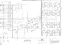
H-11-1 Schematic.jpg

This contraption appears to be driving the data bus with a pair of 74LS240s which, unless I am reading an inaccurate datasheet, do not appear to be open collector drivers.

I'm going to have to go back and study the QBus spec harder, but my initial impression was that it was terminated to somewhere around 3.3v through a voltage divider, by the CPU card (and another terminator at the other end of the bus if there were multiple backplanes chained together), and then whatever was driving the bus pulled it up to 5v or down to 0v, kinda like SCSI appears to work (but which I may also be not-understanding lol). But indeed the DS8641 is an open collector driver. But then again, what Heathkit is doing must also work. Very peculiar.

My understanding of open collector drivers is that their big advantage is being able to make wired-or connections. I can see where this would be a requirement on signals that can be asserted by more than one device at a time, interrupts, dma requests, etc. But I suppose that no more than one device at a time will ever be driving the data bus (assuming that all devices in the system are well-behaved), so perhaps that is how Heathkit is getting away with using LS240s. Generally only the CPU will be sinking the output of the memory card, with everything else tristated off the bus, so the memory card can "get away" with driving the bus high. Perhaps Heathkit's way works "well enough" in a small single-backplane system like the H11, but would be troublesome in a larger installation.

Am I on the right track here, or am I full of poo?

IIRC the TRS-80 Model II also uses the LS640 as its bus driver. Those suckers are almost $10 each these days. There has to be a way to cobble something together with more common parts that will behave "well enough". D:
 
>>> Am I on the right track here, or am I full of poo?

You are on the right track.

There is a difference between designing something to be 'correct' and designing something to 'work'.

If you limit yourself to something 'working', then a non open-collector device should be fine - providing there is nothing else attempting to drive the bus at the same time (i.e. the wire-OR bit doesn't apply). You may also find that the timing and bus-loading may suffer as a result?

However, DEC had to design things that would work to the QBUS Standards - so that other cards (designed to the same Standard) would work (even from multiple vendors).

Dave
 
Thank you sir.

Now to solve the conundrum of doing it "correctly" or "cheaply". D:

Although if I end up getting those two 2mb boards from the gentleman in Holland, it may be moot. But I guess I'd still need a >64k memory board later if I can get my 11/23 working after the H11 is finished. It would be a fun machine to run RSX-11 full time and stuff all those parallel IO cards into and use for home automation or something lol.
 
Last edited:
These Heathkit H11 systems came in at least three versions. There was an early "two switch" version of the case that lacked a front panel switch to control the LTC. Some owners modified theirs. The word is that the LTC messed up the ability to run some software and some owners added a switch. The only one I've seen with that mod had the switch mounted on the back panel of the case. Later on Heathkit switched to a three switch case with the LTC switch on the front panel. Later systems were badged as H11A. Just to make things interesting, you will find units in the middle with two switches badged as H11A.

There were also variations in the included card set. Earlier units have a quad width CPU while later ones have a dual width CPU. What caught my attention was your mention of the H11-1 memory card. My "two switch" H11 (not H11A) doesn't have one. Mine came from the original owner and came with the original mylar static protection envelopes the card set was packed in, so I'm pretty sure what I have is what was shipped, not the result of tinkering. The only Heathkit cards in it are the H11-5 serial cards and the H27 floppy controller. For memory I have a DEC M8044.

According to this:


The quad width CPU makes the unit an H11 and the later dual width CPU makes the unit an H11A. Which is puzzling, because my H11 appears to have come with the dual width CPU.
 
Yeah, that is peculiar. I have the 3-switch H11A with the M7270 LSI-11/2 CPU, 4x H-11-1 4k memory boards, 1x H-11-2 parallel board, and 2x H-11-5 serial boards (which have different part numbers on the boards themselves, but otherwise appear exactly identical, other than one has old-style flat brown carbon-comp resistors whereas the other one has newer components, as do the other Heathkit boards that came with it).
 
I looked at the H11A at the RICM today. It is a two-switch chassis with no switch to disable the LTC. It contains a M7270 KD11-HA LSI-11/2 CPU, a MSC4601 Monolithic Systems Corp. 64K RAM, two H-11-5 serial cards, and a H27 floppy controller. It came with three more H-11-5 serial cards.
 
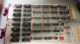
Well I started testing cards (using the QBone) with a M7944 MSV11-B 4kw RAM board. Turns out it needs external refresh, so I had to install a M9400-YA next to it to provide that. Once I figured that out, it turned out that bit 6 started getting sketchy after the thing warmed up.

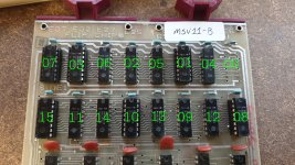
I couldn't find any schematics or layout documentation for the card, so I started making my best guess and desoldering chips one at a time (a pox upon thee, DEC, for not socketing them!). At first I couldn't see any sane pattern to how the bits were laid out, but eventually it revealed itself to be like so:

MSV11-B Bit Layout.jpg

Hopefully that will save the next guy that comes along needing to fix one of these a good bit of hair pulling and lifted traces. The adhesive on this old board is just completely shot. You even just get the iron near it and the pads start to peel up...... D: There are several fly wires on the back now that weren't there when I started, but everything still seems to work (other than bit 6 of course)....

Getting tired and grumpy, and that will just lead me to make mistakes, so I'm going to throw in the towel for tonight and finish it tomorrow. I don't have any replacement MK4096Ns anyway, so I'll have to order a handful. But I can at least verify that it is indeed #6 and not a weak bus transceiver or something for now....
 
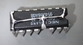
It's ugly, but I don't have any MK4096 to replace the bad IC with. But I think this modified 41256 will work......... The 4096 /CE is tied to ground on the memory card, so..... I think it will work. Lol.

20220730_221941.jpg
 
Last edited:
It's ugly, but I don't have any MK4096 to replace the bad IC with. But I think this modified 41256 will work......... The 4096 /CE is tied to ground on the memory card, so..... I think it will work. Lol.

View attachment 1244286
I love this dead-bug. Of course, it means you need to insulate it or make sure there is a space between it and the card above.
It's been years since I looked in my drawer of Q-Bus memory boards, I think I got rid of anything under 32KW, but it does my heart good to see someone caring enough about a low-density board to fix it like that.
 
Back
Top