Hi guys,
I hope I am not going to break some rule in starting a new thread about this, it could have gone maybe into that "Random characters on a PET screen" because that is the symphtom but let's go in order.
I joined this forum just today after suggestion cause "here seems the right place to be" if you are into putting back to work ( or modifying ) old computers.
But let's go with the main reason I joined this forum.
After many years me and my mate we finally managed to put hands on a Commodore PET 3032, it comes out from ebay from a guy that was treating it like "his best bet" really rarely seen such an old computer kept in such a mint condition it looks almost like "no human fingers ever touched it".
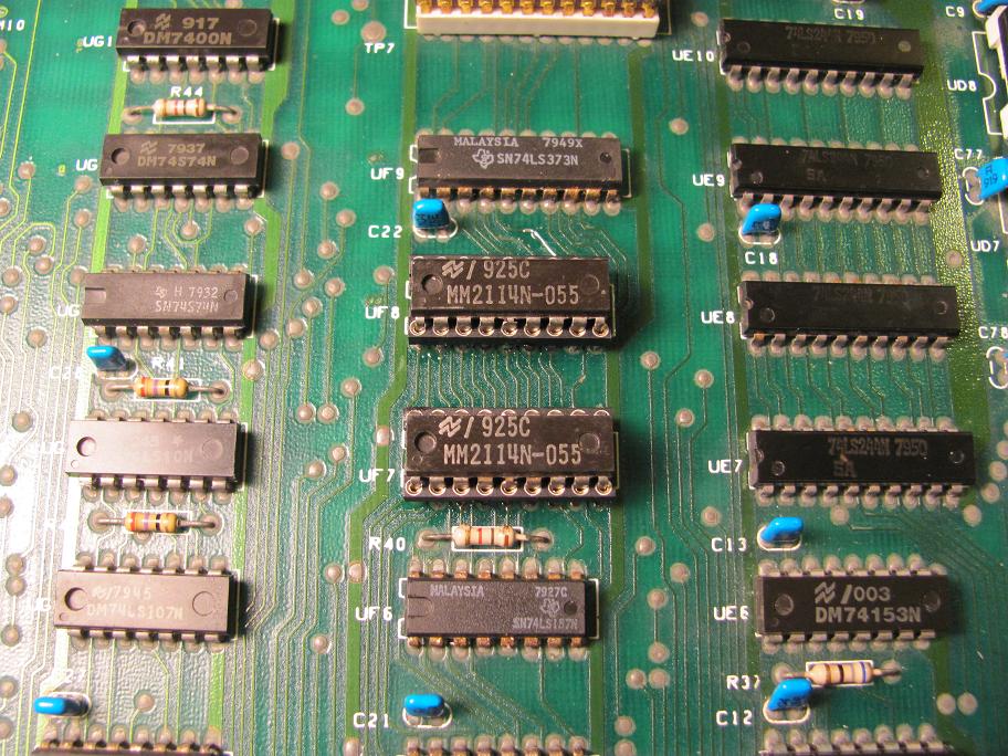
Only the motherboard had quite an amount of accumulated dust that been carefully removed by using a dry toothbrush and a vacuum cleaner centimeter by centimeter until everything was nice again.
I think this machine last time been turned on had to be around 1990 or such, it was working but the guy reported that "instead of 32K it was showing only 16K" but otherwise working fine.
It had a small incident the fuse holder got broken but I managed to fix that too.
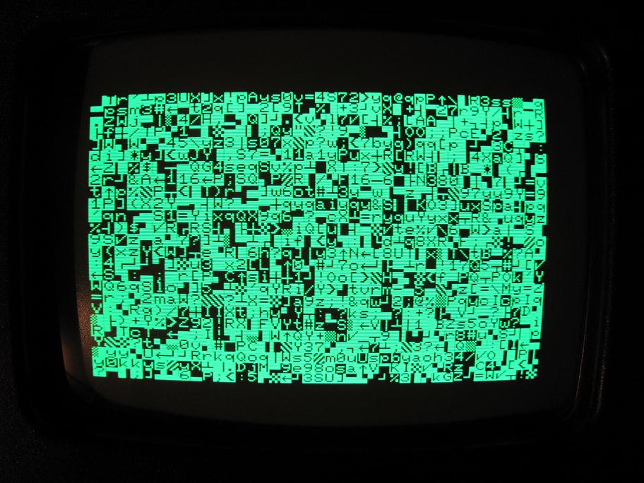
However, once started the display comes out with a really nice ( perfect condition ) picture of random garbage.
Actually "not really random" precisely is ALWAYS THE SAME "garbage" of mixed chars on screen.
After quite reading this forum we tried various things and all I could say is :
- voltages seems to be correct in all places
- the CPU receives +5v
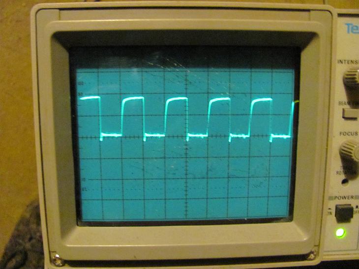
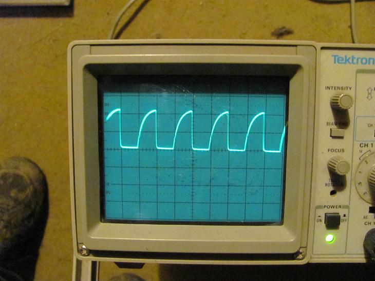
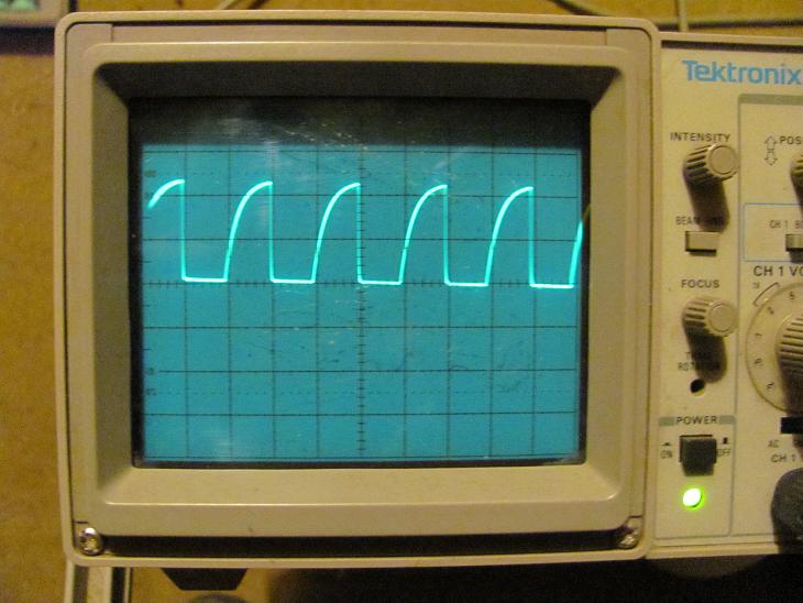
- there is a quite ok looking 5V clock about 1Mhz at pin 37
- reset line seems high
- RDY line seems high
- IRQ line is high too
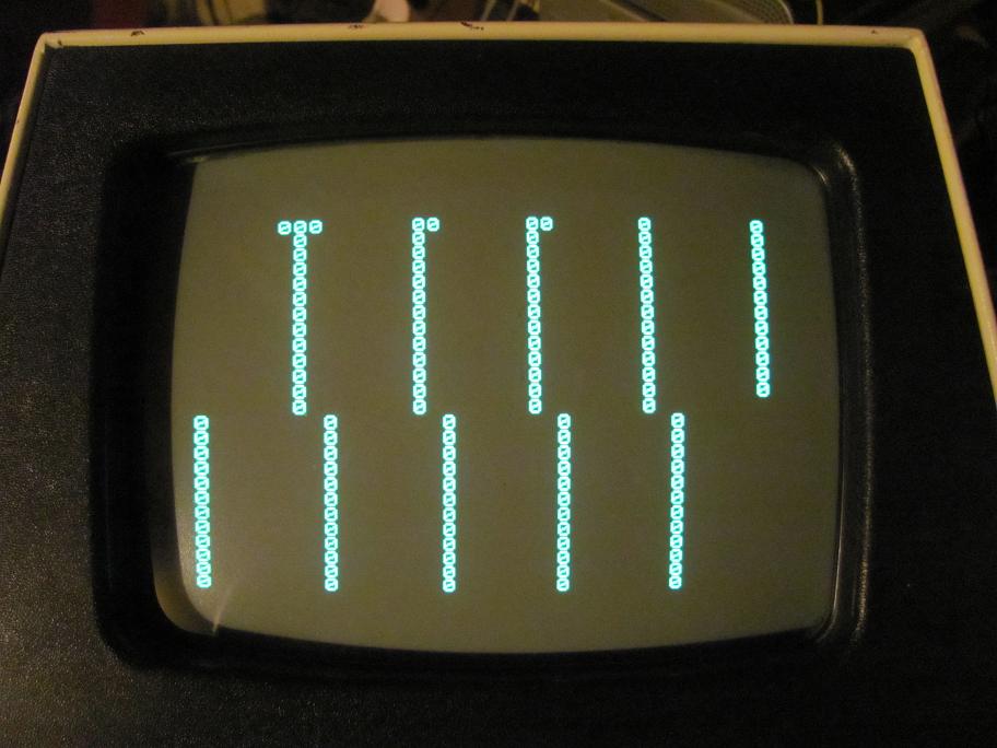
- display is perfectly stable and nice looking
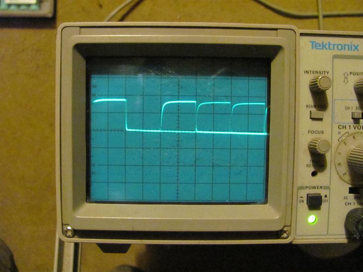
However .. all the address lines seems to be "stuck" a '1' it 'seems' like the CPU is kinda "frozen" and nothing is running, you can't see anything changing on those.
Tried to remove/reinsert chips, changed a few electrolitic capacitors, changed the crystal with a "fresh" 16 Mhz one.
No chip seems to be hotter than usual or such.
I am not sure what to think .. at some point we even tried removing ALL the ROMs to see if anything was happening, it looks like the CPU is not running at all.
I did try also to replace it with another ( it should be working ) 6502 I have spare .. nothing .. same thing.
I could/would post you ( tomorrow ) a link at some pics of it I took, you will see "everything looks now almost like new".
So it's quite puzzling .. thing is to begin to try to change some components here means "a bit of a mess" because everything is soldered directly on the PCB, I must say I never seen a CPU being "stuck" with AD lines all at 1 ..
Unless it would be waiting for some "BUSREQ" or such.
Any help would be appreciated, we really want to bring this machine back to life and be able to tell his previous owner that "the story had an happy ending".
About me huh .. there would be "even too much to say", really I got a point I actually spend more time "doing things" rather than trying to keep updated a website or blog or such about those because it would take longer than doing it.
I prefer to spend time trying to fix this poor PET")
I will only briefly say "currently messing with VDHL, CPLDs, a Z8001 and some other stuff" :D
Cheers and thanks guys in advance for any help, and remember, it's not for me, it's for that poor PET CBM that we want to bring back to life
[edit] - a few pictures ( on the links ) added.
The machine as it arrived, it is in a really mint condition apart from the dust inside :
As it arrived, a bit dusty
After patient cleaning with a thootbrush and a vacuum.
Cleaned board
Finally after replacing the fuse holder ( that was broken ) and a bit more cleaning.
More clean
I hope I am not going to break some rule in starting a new thread about this, it could have gone maybe into that "Random characters on a PET screen" because that is the symphtom but let's go in order.
I joined this forum just today after suggestion cause "here seems the right place to be" if you are into putting back to work ( or modifying ) old computers.
But let's go with the main reason I joined this forum.
After many years me and my mate we finally managed to put hands on a Commodore PET 3032, it comes out from ebay from a guy that was treating it like "his best bet" really rarely seen such an old computer kept in such a mint condition it looks almost like "no human fingers ever touched it".
Only the motherboard had quite an amount of accumulated dust that been carefully removed by using a dry toothbrush and a vacuum cleaner centimeter by centimeter until everything was nice again.
I think this machine last time been turned on had to be around 1990 or such, it was working but the guy reported that "instead of 32K it was showing only 16K" but otherwise working fine.
It had a small incident the fuse holder got broken but I managed to fix that too.
However, once started the display comes out with a really nice ( perfect condition ) picture of random garbage.
Actually "not really random" precisely is ALWAYS THE SAME "garbage" of mixed chars on screen.
After quite reading this forum we tried various things and all I could say is :
- voltages seems to be correct in all places
- the CPU receives +5v
- there is a quite ok looking 5V clock about 1Mhz at pin 37
- reset line seems high
- RDY line seems high
- IRQ line is high too
- display is perfectly stable and nice looking
However .. all the address lines seems to be "stuck" a '1' it 'seems' like the CPU is kinda "frozen" and nothing is running, you can't see anything changing on those.
Tried to remove/reinsert chips, changed a few electrolitic capacitors, changed the crystal with a "fresh" 16 Mhz one.
No chip seems to be hotter than usual or such.
I am not sure what to think .. at some point we even tried removing ALL the ROMs to see if anything was happening, it looks like the CPU is not running at all.
I did try also to replace it with another ( it should be working ) 6502 I have spare .. nothing .. same thing.
I could/would post you ( tomorrow ) a link at some pics of it I took, you will see "everything looks now almost like new".
So it's quite puzzling .. thing is to begin to try to change some components here means "a bit of a mess" because everything is soldered directly on the PCB, I must say I never seen a CPU being "stuck" with AD lines all at 1 ..
Unless it would be waiting for some "BUSREQ" or such.
Any help would be appreciated, we really want to bring this machine back to life and be able to tell his previous owner that "the story had an happy ending".
About me huh .. there would be "even too much to say", really I got a point I actually spend more time "doing things" rather than trying to keep updated a website or blog or such about those because it would take longer than doing it.
I prefer to spend time trying to fix this poor PET
I will only briefly say "currently messing with VDHL, CPLDs, a Z8001 and some other stuff" :D
Cheers and thanks guys in advance for any help, and remember, it's not for me, it's for that poor PET CBM that we want to bring back to life
[edit] - a few pictures ( on the links ) added.
The machine as it arrived, it is in a really mint condition apart from the dust inside :
As it arrived, a bit dusty
After patient cleaning with a thootbrush and a vacuum.
Cleaned board
Finally after replacing the fuse holder ( that was broken ) and a bit more cleaning.
More clean
Last edited: