• Please review our updated Terms and Rules here

Hi, new to the forum, fixing a Commodore PET

And although it's usually ignored I'm gonna suggest again that one of the most useful "tools" is a NOP generator, nothing more than a 40pin socket with pins 26-33 lifted and connected to Vcc and Gnd thusly: 55505050.

Inserted between the CPU and its socket this will continuously step through the address range and with a scope you can quickly identify bad address drivers, memory or I/O chips pulling address or data lines high or low, etc.

If power is good and the ROMs check out this is what I usually check next and more times than not it locates a problem.
 
And although it's usually ignored I'm gonna suggest again that one of the most useful "tools" is a NOP generator, nothing more than a 40pin socket with pins 26-33 lifted and connected to Vcc and Gnd thusly: 55505050.

Mike,
No wonder I ignore you, are you talking in octal? ;)

I think you mean 11101010 ($EA) for a NOP.

Actually, it is on my to-do list to make one of these. It would be a great troubleshooting aid.
-Dave
 
Last edited:
Mike,
No wonder I ignore you, are you taking in octal? I think you mean 11101010 ($EA) for a NOP.
I was referring to the voltage, i.e whether to connect to 5V Vcc or ground.

Sheesh! ;-)

Edit: Well, OK, maybe VVVGVGVG would have been clearer in the context...

Ok, connect pins 26,27,28,30 and 32 to pin 8, and pins 29,31 and 33 to pin 1. How's that, smart a$$ ? (Big ;-) )
 
Last edited:
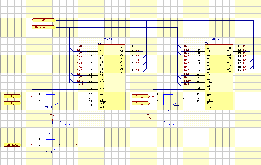
This is going to be my "weekend idea" to sort out the ROM problems.

Maybe "a bit excessive" ? ( ok I could maybe replace that 74LS00 with a 2N2222 and some little extra ).

PETRom.gif


Untested, unbuilt ( yet ) .. developed over a cup of tea.
 
This is going to be my "weekend idea" to sort out the ROM problems.

Maybe "a bit excessive" ? ( ok I could maybe replace that 74LS00 with a 2N2222 and some little extra ).

Untested, unbuilt ( yet ) .. developed over a cup of tea.
Nice; what did you use to draw that?

I don't think you have to worry about /NOROM unless you're a stickler; AFAIK only the SuperPET uses it.
But you do have to disable the upper half of the E ROM space because that's where the I/O chips live.

Let's test the ROMs first ;-)

One other point: if you ever plan to upgrade to BASIC 4.0 you would need one more chip (Bxxx) so if you do build this you might want to provide for that ahead of time; should be enough spare gates etc so all you'd need is another socket.

I did the same thing, but with one '256 chip replacing all the ROMs with two versions (V1 and V2) of BASIC using a 6540<>27xx adapter; no other chips required but if I want to upgrade to 4.0 I'd just add a 2532 for the C ROM.
 
Last edited:
But you do have to disable the upper half of the E ROM space because that's where the I/O chips live.
Never mind! I just looked at the schematic and it looks like the entire E ROM is enabled but the upper half is taken off the bus by turning off the buffers when I/O is called for, so no problem, E800-EFFF ROM data is never on the bus; on some other models the ROM itself is disabled in that space.
 
Never mind! I just looked at the schematic and it looks like the entire E ROM is enabled but the upper half is taken off the bus by turning off the buffers when I/O is called for, so no problem, E800-EFFF ROM data is never on the bus; on some other models the ROM itself is disabled in that space.

Mike,
No, you were right in the first place about needing to disable any EPROM in the E800 to EFFF memory space in the 3032 or earlier PETS or it will clash with the I/O devices. The ROM data lines (and RAM) are not buffered but are connected directly to the CPU bus.

I learned that the hard way with Stéphane's PET when I sent him a 2532 rather than a 2516 for the E000 ROM. In fact you and Anders are the guys that spotted the problem. :)
 
I did try the pin 21 thing .. Did not really do much but strangely enough while trying to see with the oscilloscope what the CPU was doing it was all looking dead.

Very odd, I tought that something would have happened.

Then taking the 6522 away again the CPU comes back to life, synch and address lines pretty active.

At this point I have to try to make some adapter and see if i can at least read the EPROMs and look what is inside.

This is getting curiouser and curiouser as I looked into the 6522 VIA and they can interrupt on transitions in the CA and CB lines or timers. So Dwight is most likely right (yet again!), since the 6522 seems to be good, it must be that the VIA initialization routine or the interrupt service routines are being messed up due to faults in ROM or RAM. Not having the system timer running properly may cause a lot of problems.
 
Mike,
No, you were right in the first place about needing to disable any EPROM in the E800 to EFFF memory space in the 3032 or earlier PETS or it will clash with the I/O devices. The ROM data lines (and RAM) are not buffered but are connected directly to the CPU bus.

I learned that the hard way with Stéphane's PET when I sent him a 2532 rather than a 2516 for the E000 ROM. In fact you and Anders are the guys that spotted the problem. :)
OK, I'm definitely gonna crawl back under my rock and have a nap now and stop confusing the issue... ;-)

Which schematic are we looking at?
 
This is getting curiouser and curiouser as I looked into the 6522 VIA and they can interrupt on transitions in the CA and CB lines or timers. So Dwight is most likely right (yet again!), since the 6522 seems to be good, it must be that the VIA initialization routine or the interrupt service routines are being messed up due to faults in ROM or RAM. Not having the system timer running properly may cause a lot of problems.
Probably another silly question the way I'm going today, but what sort of bad code would stop the CPU so that there's no sync signal or activity on the address lines?
 
I am no 6502 expert ( I know more of Z80 ) ..

I don't think there is any code that could make a cpu stop the synch or such, even if it would be running totally random bytes or a single instruction over and over I'd expect to see activity on the Synch pin and/or the address bus.

In fact "my theory" was what could stop the CPU could be :

- missing clock
- reset
- IRQ
- RDY line

As the only thing ( I think ) the VIA ( all the other 6520 chips removed ) could do was the IRQ I tought "ok, IORQ is low" .. in fact so it looks to be when the VIA is inserted, IORQ line always low.

Then I lifted the pin 21 so the VIA in theory was not able to do "anything".

However .. even in that case "the CPU was frozen" doing absolutely totally nothing.

At this point I really wonder "WHAT" makes it freeze then ?

The weirdness is that any time the CPU is "frozen" I can see clock entering in nice and coming out nice from phase 1 and 2 .. but all the other lines are "stuck" yet reset is high and in that other case ( pin 21 lifted ) IRQ was high too ..

So .. "what stops the CPU then ?"

WITHOUT the VIA chip in, you can definitely see the CPU running, there is lot of activity on the address lines and synch is pulsing.
 
Geez, cantcha have a conversation with two people at once? Personally I thought it was more effective to discuss two identical computers with similar problems in the same thread...

Hi
This type of problem will usually have any one of several different problem sources.
It will not only be difficult to post a message and let the OP know if we are talking to him
or the other fellow and once we begin really digging into it, we'll be diverging
quite a bit. It is actually better for each of the people needing help to get them either
in a separate thread or fix one in this thread first and then attack the other one so
that the time lines can be followed.
Dwight
 
I am no 6502 expert ( I know more of Z80 ) ..

I don't think there is any code that could make a cpu stop the synch or such, even if it would be running totally random bytes or a single instruction over and over I'd expect to see activity on the Synch pin and/or the address bus.

In fact "my theory" was what could stop the CPU could be :

- missing clock
- reset
- IRQ
- RDY line

---snip---
Hi
Other than reset, I think only the RDY line being low can lock the processor
up. SYNC is require to show instruction fetch. I don't think IRQ can do this.
Dwight
 
I don't think there is any code that could make a cpu stop the synch or such, even if it would be running totally random bytes or a single instruction over and over I'd expect to see activity on the Synch pin and/or the address bus.
I didn't think so either; maybe you've found the secret HALT instruction ;-)

You didn't say; can your programmer read 2716s (and therefore your ROMs)?
 
I didn't think so either; maybe you've found the secret HALT instruction ;-)

You didn't say; can your programmer read 2716s (and therefore your ROMs)?

I don't know about 6502 but in Z80 HALT basically makes the CPU continuously fetch NOP until an IRQ or a RESET of an NMI is received.

M1 ( kinda the equivalent of SYNCH ) will be always working and active even when in HALT so refresh and all the rest, plus you'd have the "HALT" pin telling you the CPU is executing halt.
 
I think a couple of undocumented (illegal) op-codes might stop the 6502. If one of your ROMs is corrupt and accidentally includes some bad op-codes, it could cause interesting things to happen.

Yup, according to this document the following op-codes are bad: $02, $12, $22, $32, $42, $52, $62, $72, $92, $B2, $D2, $F2.
http://members.chello.nl/taf.offenga/illopc31.txt

The following $x2 op-codes should work:

$82 (DOP #$nn = undocumented NOP that takes 2 clock cycles)
$A2 (LDX #$nn = official instruction)
$C2 (DOP #$nn = undocumented NOP that takes 2 clock cycles)
$E2 (DOP #$nn = undocumented NOP that takes 2 clock cycles)
 
Last edited:
Hi
It looks like any of those bad codes could lock it up.
While a bad ROM code might do this, there is also
the possibility that something is jamming one of the
data lines, causing the bad code.
Even a bad ram could cause the problem from a
subroutine or interrupt return.
I think it would be worth while to make a NOP adapter
on this machine. With his scope, he could check that
the address decoding to the various chips is
working correctly. A doubly decoded select would
also cause bad code to execute.
Next might be to write some simple test code
and blow an EPROM.
Dwight
 
I think a couple of undocumented (illegal) op-codes might stop the 6502. If one of your ROMs is corrupt and accidentally includes some bad op-codes, it could cause interesting things to happen.
Thanks, Anders; I thought I remembered something like that, in fact I think we had a PET here a long time ago that locked up like this because of a bad ROM or page zero RAM.

I still think until we read the ROMs and check the low RAM we're wasting a lot of time on irrelevant red herrings like clock waveshapes etc.

I've asked a couple of times whether the OP is just assuming that his programmer can't read the ROMs or if it really can't even read 2716s; unfortunately he hasn't seen fit to answer (nor what he used to draw that schematic, or comment on the NOP adapter that Dwight and I are suggesting... ;-) )
 
I think a couple of undocumented (illegal) op-codes might stop the 6502. If one of your ROMs is corrupt and accidentally includes some bad op-codes, it could cause interesting things to happen.

Anders,
I found this on a website that explains why the "KIL" instruction opcodes will stop the 6502:

The KIL Opcodes

There are many “KIL” opcodes, i.e. opcodes that stop the CPU, so that it can only recover using a RESET, and not even an IRQ or an NMI.

In order to understand this, let’s look at the different states an instruction can be in. After the instruction fetch, the CPU is in cycle T1. It will feed the opcode and the cycle number into the PLA and cause the rest of the CPU to carry out whatever has to be done in this cycle, according to the PLA. Then it will shift the T bitfield left by one, so the T2 line will be “1″, then line T3 and so on. There are seven T lines total, T1 to T7. At the end of each instruction, the PLA causes the T bitfield to reset, so that the next instruction starts with T1=1 again.
But what happens if T does not get reset? This can happen if in all seven states of T, no line fires that actually belongs to an instruction that ends at this cycle. T gets shifted left until state T7, in which another shift left will just shift the 1 bit out of T – all bits of T will be zero then, so no PLA line can fire any more.

All interrupt and NMI requests are always delayed until the current instruction is finished, i.e. until T gets reset. But since T never gets reset, all interrupts and NMIs are effectively disabled.
http://www.pagetable.com/?p=39


The following $x2 op-codes should work:

$82 (DOP #$nn = undocumented NOP that takes 2 clock cycles)
$A2 (LDX #$nn = official instruction)
$C2 (DOP #$nn = undocumented NOP that takes 2 clock cycles)
$E2 (DOP #$nn = undocumented NOP that takes 2 clock cycles)
My favorite 'illegal' instruction is "LAX" an instruction that loads the accumulator and the X register at the same time. It is said that gamers used some of these instructions to speed up their code.
-Dave
 
Back
Top