• Please review our updated Terms and Rules here

IBM PC Floppy Drive Problem - Head can only move in one direction

cwathen

Experienced Member
Joined
Feb 1, 2018
Messages
268
Location
Bristol, UK
My 5150 randomly stopped booting from disk (original full height Tandon 360K drive), the disk would spin but it would quickly give up and drop to BASIC.

This was quickly traced to the floppy drive itself, so I pulled the drive out and installed it on another machine as drive B:

It was unable to read any disks. I put in a fresh disk and tried to format it, it appeared to be doing so and counted up all 39 tracks but it didn't sound right (you couldn't hear the 'click' as it steps over each track) then failed on track 0 right at the end.

Taking the PCB off the top of the drive quickly revealed the problem - the head was stuck in the centre of the disk and just banging against the stop, trying to format the same track over and over again. The head assembly did freely move over the rails, so I pushed it all the way back to the outside of the disk and tried the format again in case the drive had somehow got 'confused' about where the head was on the disk.

This time it correctly formatted all the tracks but the format failed again at the end ('Cannot write boot') as the head wasn't able to move back to the outside to complete the format.

Somehow the stepper motor is only able to drive the head assembly in one direction. There is no obstruction in the head assembly's path, nothing wrong with the ability to move it by hand over the rails with power off, no damage to the stepper motor's wires that I can see either.

This one has me completely stumped, this drive has never given me the slightest problem before.
 
Did you try this with a different cable?

The floppy interface has one pin specifically for step "direction". Either your cable has developed a fault, or the input on this pin has become faulty.
 
Did you try this with a different cable?

The floppy interface has one pin specifically for step "direction". Either your cable has developed a fault, or the input on this pin has become faulty.
Doesn't this answer your question?

This was quickly traced to the floppy drive itself, so I pulled the drive out and installed it on another machine as drive B:

It was unable to read any disks. I put in a fresh disk and tried to format it, it appeared to be doing so and counted up all 39 tracks but it didn't sound right (you couldn't hear the 'click' as it steps over each track) then failed on track 0 right at the end.
 
Did you try this with a different cable?

The floppy interface has one pin specifically for step "direction". Either your cable has developed a fault, or the input on this pin has become faulty.
It's a different cable in the other computer (which did have a working 5.25" drive in that position). Just to confirm all other hardware in the 5150 is working, I've now pulled the floppy drive out of my Amstrad 1512 and put it in the IBM. All works fine. It's definitely the Tandon drive at fault.

My gut feeling is there is unlikely to be a fault with the stepper motor itself since it is working perfectly in one direction, but no idea what is then at fault!
 
My first gut feeling is not the stepper, but the driving circuitry. You can't step with just one set of coils operating--the shaft will not move at all.

A good tutorial on steppers

I believe there are Sams Photofacts for the Tandon TM-100 available that should be a great help.
 
My bet is a stuck or broken track 0 switch. It thinks it is always at track zero and that won't let it go any more towards track zero, it is locked out by 4F pin 10 being stuck low.
Dwight
 
My bet is a stuck or broken track 0 switch. It thinks it is always at track zero and that won't let it go any more towards track zero, it is locked out by 4F pin 10 being stuck low.
Dwight

Good suggestion. I was wondering that if 4F pin 10 was stuck low, it wouldn't inhibit the clocking of both flip flops and not affect both directions, not sure but worth checking as it could be a number of problems.

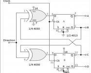
The circuit that sets the direction uses two XOR's in a common configuration (attached) used for stepper motors with center tapped coils. So it could be one of those XOR gates or the LS 04 gate too
 

Attachments

  • stepper.jpg
    stepper.jpg
    69.3 KB · Views: 1
Last edited:
My bet is a stuck or broken track 0 switch. It thinks it is always at track zero and that won't let it go any more towards track zero, it is locked out by 4F pin 10 being stuck low.
Dwight

Opps. I should have said 4F pin 10 stuck high not low. When both pins of 4F were one, it would block the step pulse. Anyway, the same problem the switch is stuck or something in the switch path. 4F only blocks the steps when it tries to go towards the track 0 position.
The problem could also be 3D, 4B or the other two sections of 4F used for the input latch.
It is more likely the switch with the NC contacts not making, causing the input latch to stay on track 0. Old mechanical parts are more likely to fail than ttl.
It was late and I wasn't thinking.
Dwight
 
Good suggestion. I was wondering that if 4F pin 10 was stuck low, it wouldn't inhibit the clocking of both flip flops and not affect both directions, not sure but worth checking as it could be a number of problems.

The circuit that sets the direction uses two XOR's in a common configuration (attached) used for stepper motors with center tapped coils. So it could be one of those XOR gates or the LS 04 gate too

It could be one of the XORs or 3D but my bet is still with the Zero switch. He didn't say it would step away from track zero when it was suppose to be stepping towards track zero, only that it would only step the one way. I assume, that meant it was not stepping at all when it should step to zero. If it were the inverter or the xor, the drive would never go ready and reset would hang waiting for track00 signal. He didn't say that reset was hanging but then he didn't say there was an issue with reset, requiring him to push the heads back manually( a missed reported symptom ).
Dwight
 
This is getting odder and odder.

As luck would have it, an identical Tandon drive turned up on eBay which I've now picked up. I was still hoping to repair the other drive to finally make it a 2 drive system.

The track 0 switch is working fine, and the head assembly is activating it when pushed back. I then swapped the PCBs over between the two drives and expected the original drive mech to work with the new drive's board. It doesn't. Same problem of the head only moving in one direction.

So I'm looking for a problem with the mech other than the switch!
 
You need to trace the track00 circuit. 4F pin 11 should track the switch. Watch T8. It should not toggle when the head is moving away from track00 and should stay high.
Like wise 3D pin 2 should stay low.
It is possible for a blown drive to miss one phase and only work in the one direction.
Dwight
 
Last edited:
Depends on the number of wires. TM-100s were made with both 4 and 6-wire steppers. I could see a 6-wire stepper only working in one direction, but they weren't the most common variety in TM-100s.
 
Time to invest in a logic probe then and have more of a play!

One thing I have noticed is that when the head reaches the centre and starts banging against the stop, it does move back (what appears to be) one track after each attempt before the next attempt to move the head where it will hit the stop again.

Is this the stepper moving the head back in a controlled way (in which case a fault with it can be ruled out) or is this just a mechanical action from the stop that knocks it back?

This part of the circuit can be tested with a voltmeter and a piece of wire, you don't need a logic probe.
It will jump back if it is stopped before it advances again. The is not that it is trying to backup, it is because being held it eventually reaches the first step of the opposite direction.
Dwight

Dwight
 
Back
Top