Hi,
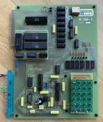
I have just completed building a new KIM-1 Rev.D replica board. This is a project I have been wanting to build for quite some time and now it’s finally finished (at least the soldering part) .
.
I do however have some issues getting it to work. The problem is that I get no output on the display even after hitting the reset button on the keypad.
I have connected pin ”K” to ground to enable internal address decoding since I am not using anything other than the KIM-1 itself right now.
I have inspected and tested every TTL IC and RAM IC and they all work fine so they should not be the cause of my dead KIM-1. I have also verified that I have a working 1 MHz clock signal on the board using an oscilloscope, so the only IC's that have not been tested are the CPU and the 6530-replacement board I am using. The TTL IC’s on the 6530 replacement board have also been tested and I have tested two pairs of different 6532 IC's.
I know that the MAN72A displays are working since they are NOS parts and I verified all of them on a breadboard before soldering them to the board.
The power consumption of the board is about 0.8A with the dual 6532 -> 6530 replacement board connected.
I also have a question regarding resistors R18 - R23. According to the KIM-1 user manual they are supposed to be 220Ω resistors (which is what I used in my build), but I have noticed that later variants of the KIM-1 (Rev. D and newer) uses 100Ω resistors instead. Why did they change the resistor value and does it matter if they are 100Ω or 220Ω?
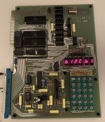
I would really appreciate any advice that would lead me to a functional KIM-1. I include an image of my build to make it easier for any of you KIM-1 experts to check if there is any obvious fault on my board.
Thanks!

I have just completed building a new KIM-1 Rev.D replica board. This is a project I have been wanting to build for quite some time and now it’s finally finished (at least the soldering part)
I do however have some issues getting it to work. The problem is that I get no output on the display even after hitting the reset button on the keypad.
I have connected pin ”K” to ground to enable internal address decoding since I am not using anything other than the KIM-1 itself right now.
I have inspected and tested every TTL IC and RAM IC and they all work fine so they should not be the cause of my dead KIM-1. I have also verified that I have a working 1 MHz clock signal on the board using an oscilloscope, so the only IC's that have not been tested are the CPU and the 6530-replacement board I am using. The TTL IC’s on the 6530 replacement board have also been tested and I have tested two pairs of different 6532 IC's.
I know that the MAN72A displays are working since they are NOS parts and I verified all of them on a breadboard before soldering them to the board.
The power consumption of the board is about 0.8A with the dual 6532 -> 6530 replacement board connected.
I also have a question regarding resistors R18 - R23. According to the KIM-1 user manual they are supposed to be 220Ω resistors (which is what I used in my build), but I have noticed that later variants of the KIM-1 (Rev. D and newer) uses 100Ω resistors instead. Why did they change the resistor value and does it matter if they are 100Ω or 220Ω?
I would really appreciate any advice that would lead me to a functional KIM-1. I include an image of my build to make it easier for any of you KIM-1 experts to check if there is any obvious fault on my board.
Thanks!


