• Please review our updated Terms and Rules here

Lanier Model 103 "No Problem" word processor

Yes, your imagination is probably pretty close to the mark.

The power supply alone weighs about twenty pounds.

With everything inside, it takes two people to lift this machine and move it about safely.

Phil
 
Hooked it all up and the 5V rail operates at about 2.2V under load so something's causing the crowbar circuit to kick in. I'm going to start by looking at the Zener that controls it.

--Phil
 
Hooked it all up and the 5V rail operates at about 2.2V under load so something's causing the crowbar circuit to kick in. I'm going to start by looking at the Zener that controls it.

Maybe you could just retrofit a modern switching power supply, instead of spending your time diagnosing the cranky old linear PS?
 
Yeah, it's a beefy supply. I could power up with +12, +5, -12 from a regular supply, but this one also puts out +15 and -15.

It's been stored up for ages, so pushing it back into service will undoubtedly show up a few faults and troubles initially, especially in older silicon and germanium.

It's slow-going because it's just being worked on in spare time. Also allows for the frustration to be spread out, which is a good thing; I can walk away from it for a week and cool off, then go back to it whilst not so annoyed it broke again.

--Phil
 
ok, it's not the zener that controls the crowbar.

Got something else gone bad somewhere. Got a couple possible culprits, going to work on that one.

--Phil
 
Frustratingly, the 5v line isn't regulating. It just increases in voltage until the crowbar kicks in. Replaced an electrolytic across the rail and the NPN that runs the chopper signal to the voltage regulator chip.

No joy

Going to carry on, having changed the regulator chip and pulled the main diode and filter cap.

The rest of the board doesn't come up until the voltage trips out.


Phil
 
Having a thought on this overnight

There are 4 choppers, independently controlling either a +27 or -27V supply, three are positive rail supplies, for +5, +12 and +15V

The other is -15V with a separate regulator that bleeds off the -15 supply to create -12.

+15 and -15 are only for the printer.

The +12 and -12 rails have to come up first, the +5 rail chopper is padded with a 100 Ohm resistance, presumably to cause it to come up after the +12 and -12 rails.

However, what's happening is the +5 is wide open (as if the chopper were short) and the clock doesn't come up to provide the chopper signal until the +5 has tripped out on the crowbar. I need to check see if the chopper is being held (or pulled) open by a false signal from somewhere because I don't know why it's rising up so quickly before the other circuits become active- the others don't come on until the clock starts to operate.

The more I think about it the more it makes sense, but the less it does because I can't see why the signal should be operational until the clock becomes active.

Result- the +5 comes on, rises to about 5.8V then kicks out, the rest of the board becomes active and the +5 chopper and crowbar get really rather warm.

I'm thinking this is a problem the board's had for a while...


--Phil
 
Replaced a few of the tin-can TO-18 2N2222A transistors as a number had tin whiskers present on the exterior of the cans. Changed a couple of the orange tantalum capacitors as two were showing cracks.

Had a poke about through the circuit and saw that the gate of the chopper transistor assembly was not being modulated by the clock signal.

Dave, you were right, something had gone short- one of the brand new (old stock) transistors.

Replaced that and bingo:

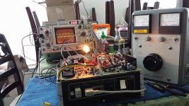
20150329_174115.jpg


Found another bad transistor that was causing the clock to load down and run too slowly, making the assemblage whine. Now it's good, though there's a bit much DC ripple on two of the rails (+12 and +15) so I'm in for a couple new main filter caps I think.

--Phil
 
Last edited:
I'd load the rails down and run it out of the machine for a few hours or even a day to see if anything else fails, especially if you're running into NOS parts trying to give you the slip.
 
I think I might, I have a few light bulbs I can use for the task.

I've ordered the other filter capacitors, as the ripple is about 0.25V on the +12 and +15 rails, as mentioned. I'm going to wait until those come in (should be next week) before benching it.

--Phil
 
Capacitors still en route, but a little testing began last night.

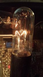
20150401_201430.jpg

A suitable set of loads, drawing about 200mA on each rail. Makes for good mood lighting.

--Phil
 
Last edited:
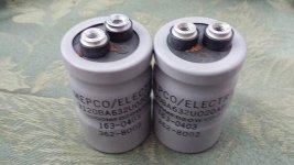
20150403_124858.jpg

Slightly blurry picture but those caps have seen better days. Replacements have seen the ripple on the appropriate lines quenched; it would seem it needs a few more now after running it a few hours. Typical.

At $14 a pop, it'll have to wait a little while.

Phil
 
Last edited:
Positive things occurring. Slightly.

Powering the thing up now liberates slightly less than it did before, however, the CAPS LOCK light comes on (doesn't go off again though) if the button is pressed.

Putting a regular soft-sectored floppy disk in causes most of the data/address lines etc on the 8080 to flicker in a repeating -_-_-_-_-_-_- pattern

It doesn't CLUNK and pull the heads in any more though (mind you, I did clean the floppy drives), and the lights don't come on.

Nothing on the screen either.

However, it's back up and into a place whereby I can start poking around to check see what's happening. Need to figure out what direction to go in.

--Phil
 
I'll pull the keyboard off and check see with it all unhooked that the keys are stuck etc.

The display is just turned up to full intensity, so the raster is visible. That way at least I know it's on and it's actually giving vertical timing.

It's the wrong kind of floppy, but it does have data on (random disk that I was using with my TRS-80) so it has no timing hole in the right place, so on, so forth. But, it's making it from the IO board, across the bus to the CPU.

--Phil
 
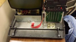
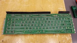
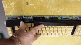
Removed keyboard, cleaned detritus out from chassis.

20150406_140301.jpg

Took a look at the board, it appears to be a fairly standard keyboard, manufactured by Honeywell.


20150406_140318.jpg
20150406_140407.jpg

Tried probing the key-switches with my meter, I'm not sure if these are capacitive type ones or what because the meter doesn't show any difference in ohms across the pins when the keys are pressed.

However, for giggles, I decided to power it up with the keyboard disconnected. Joy! Raster comes up, vertical sync comes in, them BEEEEEEEEEEEEEEEEE from the loudspeaker. Pressing reset makes it go quiet, then come back once the raster stabilizes.

It's partly alive, it knows the keyboard isn't there :)

--Phil
 
Last edited:
There are a number of chips on the keyboard, so I'm going to hazard a guess it'll be some form of decode and pass interface.

The beep would also appear to have been there all the time- the loudspeaker plug wasn't fully pushed home, and the thing fell off the pins just earlier. I replaced the keyboard, and the constant beep is still present.

Putting a disc in either drive causes the beep to become staccato, beep beep beep beep.

CAPS LOCK LED appears to be driven by the keyboard circuitry.

--Phil
 
I've not had much of a chance to do anything in terms of diagnostics on the keyboard- I can try have a poke about with it powered up to see if there's anything resembling data transfer with it in operation, keys being pressed.

I'm thinking possibly it's kinda mostly sort of doing things but the video output is not functioning.

I was going to have a poke about on the video lines- it seems to be a fairly standard interface to the Motorola circuitry so one of the lines should be brightness- applying a signal to that line should result in patterns or noise on the screen. That would show the video circuitry is responsive to a brightness signal and should be able to draw on the screen. Right now that's an unknown. It would appear that the screen is mostly working though.

Disconnecting the video signal from it and power it up leads to a very bright, unstabilized raster. Plugging it in provides a raster that's uniform and stable. I shall poke at it and see what the sync looks like- it would seem to be issuing a sync and refresh signal so I'd say that section of the video card is operational- refresh, count 80, refresh..

--Phil
 
Hm, good idea. The monitor assembly does have a part number, I'll go look at that.

Good idea on the video DRAM. I've pulled up the datasheet.. should be able to hold data in high and see if I get an output. Then the same with data out if not. Then trace that forward to see what puts out to the monitor.

Thanks

--Phil

EDIT: The monitor is an M4000-601, according to the label.
 
Last edited:
Back
Top