Shadow Rom Banking the 8KByte EEprom as a 512Byte Prom:
I've updated this message is the improved use of JP (HL) as the single byte opcode to use in the EEprom Page change block.
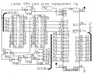
Below is a schematic for a small Lanier 103 CPU Card 20pin Prom socket to 8KByte EEprom plug-in. It uses a two-stage capture off the address bus to supply sixteen page addresses for the 8KB EEporm, residing in the 512B address page of the original prom. A single stage might suffice but as we don't have a schematic, this two-stage design works safely.
The concept is that the rig detects access to the highest 16 bytes of the 512byte prom address space. When A4-A8 are all high, and CS# is active low, the program counter has addressed that range of 16 bytes. The *trick* is to capture the low address lines A0-A3 (nibble) and latch them in as the page select A9-A12 on the EEprom. Thus the selection of 1 or those 16 bytes in high prom space, will set the page address to the EEprom when that cycle is over.
For example, access to address 01Fx will the the page of the EEProm to the nibble value x. Thus 01F0h selects page 0 or 15, 01FCh selects page 12 of 15, and 01FFh selects page 15 of 15. The trick is to not switch the page until that access is completed, thus when CS# and A4-A8 all being high, deasserts, that's when the EEprom page is updated. As it needs A4-A8 as they're disappearing, the two stage latch is used to temporarily hold A4-A8 anytime CS# goes active on the prom, holding it in the first stage. That value is never used unless the current access is to the high 16 bytes of the prom, which triggers a LOW signal to the second stage latch, that clocks in the address saved on the first stage latch as CS# and A4-A8 deassert at the end of the access cycle. That updates the EEProm page.
That's the hardware side.
On the firmware side the access to the 16 byte page select range, needs to have a single byte instruction that changes the program counter out of the range afterwards. Previously I discussed RST N and RET instructions and how they'd be used. As both require a dummy stack operation, I've realized that using a JP (HL) instruction is more advantageous. Its single byte, Z80 and 8080 instruction, and it allows a jump to any address in another page, as the code example below will illustrate. If the current page is loaded into a register other than HL, a call can be made to a routine in another page, and it can use the register to find its way back. I'll add a code example to illustrate that too.
Code:
;every 512byte page would have this at the top 24 bytes FROM 01E8h-01FFh:
		ORG		01E8h
		;E holds previous page as F0-FF value
01E8H	1601	PAGRET:	LD	D,01h		;high page select address 01Fxh for accessed by dummy return
01EAH	D5		PUSH	DE		;setup return address on stack prior to RET goes to PAGEx
01EBH	21EE01		LD	HL,RETURN	;routine to execute in the destination page
01EEH	C9	RETURN:	RET			;enters PAGEx via the return address on the stack
01EFh	F0	PAGE:	DB	0F0h		;address of current selected page of EEProm
01F0h	E9	PAGE00:	JP	(HL)		;select page 0 of 15 and execute code at (HL)
01F1h	E9	PAGE01:	JP	(HL)		;select page 1 of 15 and execute code at (HL)
01F2h	E9	PAGE02:	JP	(HL)		;select page 2 of 15 and execute code at (HL)
01F3h	E9	PAGE03:	JP	(HL)		;select page 3 of 15 and execute code at (HL)
01F4h	E9	PAGE04:	JP	(HL)		;select page 4 of 15 and execute code at (HL)
01F5h	E9	PAGE05:	JP	(HL)		;select page 5 of 15 and execute code at (HL)
01F6h	E9	PAGE06:	JP	(HL)		;select page 6 of 15 and execute code at (HL)
01F7h	E9	PAGE07:	JP	(HL)		;select page 7 of 15 and execute code at (HL)
01F8h	E9	PAGE08:	JP	(HL)		;select page 8 of 15 and execute code at (HL)
01F9h	E9	PAGE09:	JP	(HL)		;select page 9 of 15 and execute code at (HL)
01FAh	E9	PAGE10:	JP	(HL)		;select page 10 of 15 and execute code at (HL)
01FBh	E9	PAGE11:	JP	(HL)		;select page 11 of 15 and execute code at (HL)
01FCh	E9	PAGE12:	JP	(HL)		;select page 12 of 15 and execute code at (HL)
01FDh	E9	PAGE13:	JP	(HL)		;select page 13 of 15 and execute code at (HL)
01FEh	E9	PAGE14:	JP	(HL)		;select page 14 of 15 and execute code at (HL)
01FFh	E9	PAGE15:	JP	(HL)		;select page 15 of 15 and execute code at (HL)
Example: In EEprom page 4 it needs to jump to address 0B8h in page 12.
Code:
P04:		218000		LD	HL,GETCHR	;load the address of function on another page in HL
P04:		C3FC01		JP	PAGE12		;go to 01FCh to execute JP (HL) and switch to page 12
P04:	01FCh	E9	PAGE12:	JP	(HL)		;load the destination address into the program counter
P12:	0018h		GETCHR:				;Page 12 is loaded by hardware as the previous instruction is fetched.
						;execution continues within page 12 and the address of function GETCHR.
To do a call and return, the current page is loaded into a register for the function to utilize:
Code:
P04:		1EF4		LD	E,0F4h		;load return page number
P04:		211800		LD	HL,GETCHR	;load the address of the other page function in HL
P04:		CDFC01		CALL	PAGE12		;go to 01FCh to execute JP (HL) and switch to page 12
P04:	01FCh		PAGE12:	JP	(HL)		;load the destination address into the program counter
P12:	0018h		GETCHR:				;Page 12 is loaded by hardware as the previous instruction is fetched.
P12:	...	C3E801h		JP	PAGRET		;return to original page in E and return address on stack
P12:	01E8H	1601	PAGRET:	LD	D,01h		;high page select address 01Fxh for accessed by dummy return
P12:	01EAH	D5		PUSH	DE		;setup return address on stack prior to RET goes to PAGEx
P12:	01EBH	21EE01		LD	HL,RETURN	;routine to execute in the destination page
P12:	01EEH	C9	RETURN:	RET			;enters PAGEx via the return address on the stack
P12:	01F4h		PAGE04:	JP	(HL)		;load the destination address into the program counter
P04:	01EEH	C9	RETURN:	RET			;enters PAGEx via the return address on the stack
P04:	(original return address)
Here's the schematic updates:
(1) Lanier CPU prom adapter2.jpg
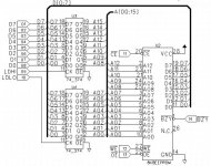
(2) Lanier Arduino EEprom Burner2.jpg
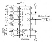
(3) Lanier Arduino Dram Tester2.jpg
(1) Shows to two-stage address latch.
(2) Shows the previous updated with I/O counts and bus lines for clarity.
(3) Shows the previous updated with I/O counts and A7 added for 64Kbit Drams too.


")