• Please review our updated Terms and Rules here

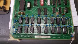
Lanier Model 103 "No Problem" word processor

What I had seen until now- power up. Screen comes on to raster. Continuous beep from speaker. Blank screen. Drive motors spin continuously.
Insert (soft sectored) floppy disk, in either drive. Beep beep beep beep beep so long as the disc is in. Blank screen.

Previously, the lower drive would CLIK and engage the read/write head mechanism (head clamp) but would not move the heads.

Pressing the reset button causes raster to de-stabilize then come back to a rectangle, beep resumes about 1/4 second later. Blank screen.


What others have said- "It beeps until you give it a disc. If the disc you give it does not contain boot code, it would fill the screen with 0 or 1 depending on the drive you put the wrong disc in"

--Phil
 
JD- Do you have the chip listing spreadsheets I sent you? The ones I have here became corrupted due to a faulty program.

--Phil
 
PhilipA said:
...others have said- "It beeps until you give it a disc. If the disc you give it does not contain boot code, it would fill the screen with 0 or 1 depending on the drive you put the wrong disc in..."

Good. Odds are high that the reason your's doesn't get that far is that Dram has problems and thus all stack activity is like a ramdomizer, particularly the RET instructions. :)

We might consider a expanded Prom replacement that allows us to test Dram and other parts of the system before doing stack operations. If we limit the code to 512bytes, we might not be ready to know how to write to the screen and control scrolling correctly, for now.

That they said the screen filled with a number, suggests strongly that the Video Dram *IS* the 8000h-BFFFh block... though the code above only fills 8000-9FFFh.

The 32KB on the CPU card, I'm hoping is 0000h-7FFFh and that they shadow that ROM in until the Boot rom jumps to 8000h, where a snippet of code flips the Boot Rom out of the Memory map and the completes the boot loader to transfer to system software into that 32KB block, quickly transferring execution off the video page and shortly clearing that and posting the Welcome page on the screen.
 
Last edited:
Hopefully when it comes in, I'll try changing out the RAM on the CPU card and see what results that yields. That's a low impact effort, might show up if that's the problem.

I'll agree with you it's highly likely.

I might try do a RAM tester on the Arduino, it might run fast enough for the RAS/CAS to work


--Phil
 
...or not, the 4116 is out of stock. Please call back May 1st.

Time to start RAM testing, I think.


EDIT: Looked on the vintage arcade game scene and discovered that 4164 is nearly pin-compatible with 4116- clip off the -5V supply pin and tie the MSB address line low, and it's a slot-in replacement.

Ordered that instead, should be arriving sometime soon from The California.


--Phil
 
Last edited:
PhilipA said:
...4164 is nearly pin-compatible- clip off the -5V supply pin and tie the MSB address line low...

A 64KB Dram may work as you describe. The CPU card's refresh circuit will only keep a fractured (not internally contiguous) 16KB block refreshed.

Drams capacity jumps in powers of 4 because the address is split in half and latched separately as a row and column address.

For a 16KB Dram, A0-A6 and A7-A13 are the two halves that are latched into the Dram for normal access. A 64KB Dram is addressable A0-A15, and the split would be A0-A7,A8-A15. When you tie that MSB low (or high if it goes bad, a second chance) you'll actaully address it oddly:
Code:
8080   +-------+             +----------+
Addr   |       |             | 64KB Dram|
A00----|       |---A00&A07---|A00&A08   | Addresses used in a 64KB Dram:
A01----|       |---A01&A08---|A01&A09   | 0xxxxxxx.0xxxxxxx
A02----|       |---A02&A09---|A02&A10   | Thats every other 128 byte block
A03----| Dram  |---A03&A10---|A03&A11   | up to the 32KB boundary.
A04----|Refresh|---A04&A11---|A04&A12   | Nothing above 32KB, inside the Dram
A05----| Chip  |---A05&A12---|A05&A13   | would be addressed or refreshed.
A06----|  &    |---A06&A13---|A06&A14   |
A07----|Circuit|       GND---|A07&A15=0 | Refresh would happen on the entire
A08----|       |---RAS-------|          | lower 32KB block, though you can't
A09----|       |---CAS-------|          | access but half of it.
A10----|       |             +----------+
A11----|       |
A12----|       |
A13----|       |
       +-------+
Note that if you tie the old -5Vdc to TTL High instead of GND, you have a backup 16KB set in the DRAM's high 32KB that you can *try* should you have bit problems later.

When its tied to TTL high, the effective address inside the 64KB Dram is 1xxxxxxx.1xxxxxxx And the upper 32KB should be refreshed. So that's *why* it should work.

By the way, instead of modifying every Dram, it would be better to just cut the -5Vdc trace feeding those chips and jumper the isolated side to GND or TTL High (GND is better given that choice). That way you don't ruin you Drams and you can use them is something else if you get some 16KB Drams later. Just one cut trace and wire tack to reverse. :)
 
Last edited:
It should- I know it's a bit of a waste- I don't intend on using it all, I have ordered most of it for another machine that actually takes 4164.

To use a 4164 with the address line tied off is a tested* trick used where 4116 is unavailable.

Should be able to start with one and sequence through- then two. I know it's a lot of combinations but it's a direction to go for now. I forget how fast the RAM has to be strobed to keep it "alive". More thinking along the lines of building an ad-hoc tester with the Arduino..

--Phil

*not by me, yet.
 
Last edited:
I've seen Drams done like that before, but I wanted to actually figure out what memory was being addressed internally and confirm that the refresh would be fine. Not really an easy way to to paging except to toggle the TTL level on the MSB address (as opposed to hard tying it to GND or TTL High.

I'll look to see if my datasheet download has the timing information for the refresh and RAS/CAS (row/column) latching of the address for your Arduino Dram tester. If I don't find it tonight, I'll dig for it Thursday afternoon (after a meeting).
 
No problem, no rush at this instant. The replacement DRAM is currently in San Fransisco. I'm hoping it'll be here Friday or Saturday.


Thanks

--Phil
 
My recollection of the Lanier 8" machines was that a USART/USRT was used for floppy, with a bit of Fairchild Macrologic for CRC generation and checking. Of course, this means that the bit ordering is "backwards", but otherwise pretty straightforward M[sup]2[/sup]FM encoding.
 
My concern is the Arduino won't run fast enough on the code loop. I was doing some calculation and it might be a problem.

However, it could be of use to program boot code onto some form of EEPROM or flash.

It's doing -something- because recall, stuffing a soft-sector floppy into either drive causes the beep to repeat on and off rather than just the solid on that it does. So some signal is getting from the I/O card that's forcing it to interrupt.
I'm good with attempting to tie the floppy cables to force it to advance and see if it produces any screen output. That would be a good indication. I'm concerned that the drive heads no longer pull in, but that might be just me. I know the mechanism is working because it'll CLUNK in and out rapidly on power-down.

--Phil
 
Being on the West Coast, if you have any chips you want to read or burn that are within what a Willem can support, I can do that for you.
 
The beeper is on the addendum card that's attached to the top of the backplane. There's a plugin for the loudspeaker.
 
Photos I shall work on, I'll need to get a couple suitable lights and an area to photograph in. I'll work on that in the upcoming week.

CPU DRAM - of the 18 chips I put in the Compaq, 6 were faulty in some way or another. Testing the DRAM in this will be vital. Would also be helpful to test the original 4116 RAM.

Programming EEPROMs - without hardware additions only 512 bytes with the number of address lines. I might save up and buy a larger Arduino, with a greater number of I/O pins, so it can work natively with pretty much anything that can be attached to it.


--Phil
 
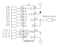
The image below shows a concise way to do the 16Kx1 Dram tester on your Arduino.

As you probably want to test your new 64Kx1 Drams too, just reserve your D0-D7 for the test socket's A0-A7 lines instead and read and write to DIN DOUNT by another bi-directional I/O bit.4

Initialize by doing a refresh cycle for all 128 rows of the 16Kx1 Dram or 256 rows of the 64Kx1 Dram. Effectively you load 00h on A0-A6,A7 and activate RAS# to refresh all the cells on that row, then increment the address and RAS# it again. The timing should be in the spec, I'll get that later. After you've done all the 128 or 256 rows depending on which Dram you're testing, set a timer in the Arduino to alert your code when to do another refresh.

In the period between refreshes could can read and write a single bit by latching the 16K or 64K address in two steps. The manual will say which you do first but I'll assume is Row for High half of the address and Column for the Low half of the address. I'll edit a correction when I dig up that datasheet.

The datasheet will tell you when to activate the WRITE# to determine whether its a read or write cycle.


All these signals can be chosen from your 18 I/O lines with the exception of the odd voltages lines. D0-D7 would be better on a single 8bit port.
 

Attachments

  • Lanier Arduino Dram Tester.jpg
    Lanier Arduino Dram Tester.jpg
    48 KB · Views: 1
Last edited:
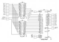
The schematic below shows an example of how to do the EEprom programmer on your Arduino, just adding two common 74'374 to latch the high and low address lines from the same data bus used to read and write from the EEprom.

Using loadable counters doesn't really add much so latching is really better when you consider that the chips are more common.

All these signals can be chosen from your 18 I/O lines. D0-D7 would be better on a single 8bit port.
 

Attachments

  • Lanier Arduino EEprom Burner.jpg
    Lanier Arduino EEprom Burner.jpg
    84.2 KB · Views: 1
Back
Top