• Please review our updated Terms and Rules here

Model II,12,16,16B,6000 8" to 5.25 Inch floppy adapter cable 50 pin to 34 pin

I did splice together 2 floppy cables a 50 pin to a 34 pin although I did not have much luck getting it to work the motor was off until I inserted a disk and closed the drive latch. Then the motor came on. Sounds like that is what should happen. So I think.

Sounds right.

Also even with an external drive configured as drive DS1 the system will always want to boot the internal drive no matter what. So I can't boot from the external unless I hook it up to the internal connector? Which makes sense. Then put the internal drive on the external connector? Then boot the 5.25 connected to the internal connector. And the 8" will be the external drive as DS1. The I can transfer files from the 5.25 to the 8". Or am I way off course. Let me know.

That sounds right with one addition: You'll also need to change the jumper on the internal drive from DS0 to DS1.

Mark: is the PDF schematic current? I was wanting to build an adapter according to your diagram.

I would not trust my schematic just yet. It's under active development, and I threw out that first draft for y'all to find my mistakes. ;)
 
I don't know yet whether it's any good or not. That's the whole point of sharing it: getting more eyes on it to see if I've messed anything up.
 
Also even with an external drive configured as drive DS1 the system will always want to boot the internal drive no matter what. So I can't boot from the external unless I hook it up to the internal connector? Which makes sense. Then put the internal drive on the external connector? Then boot the 5.25 connected to the internal connector. And the 8" will be the external drive as DS1. The I can transfer files from the 5.25 to the 8". Or am I way off course.

Also change jumper on internal drive to DS1 from DS0. Oops, I see that was covered...
 
Here's an update of my work in progress. I'm still hoping for feedback on the motor control jumpers.

This draft includes four zero-ohm resistors which may be removed if it is desired to remap the drive selects. I also decided that having connectors on both sides was ugly, and I shrunk the PCB size a little bit.

https://dl.dropboxusercontent.com/u/29876211/fd50to34-draft-02.pdf

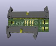
fd50to34-draft03.jpg

Comments?

Note: This is still a ROUGH DRAFT of WORK-IN-PROGRESS. Don't trust it yet!
 
Well, I'm going for broke and having boards made. It'll work or it won't! :)

Project files are up on Github:


Key differences from previous drafts:

  • Drive select remapping resistors are shorted out on the top layer. No need to install resistors or wires for the default mapping. Cut the exposed traced under each resistor if remapping is necessary, then solder on wires to scramble the drive selects as desired.
  • All drive signals are labeled on the bottom silkscreen. Maybe I even got the labels right?
  • Since I was too impatient to wait for expert feedback on the motor control jumpers, I documented them as "untested" and rolled the dice.
 
Last edited:
And, I found the first error while glancing at the picture that I tweeted: Dyslexia in the silkscreen. DOH!
 
in 2 diagrams I have pin 16 on the 5.25 to pin 18 on the 50 pin side. Which you account for by way of jumpers.

That's reassuring, then, because I just wild-guessed that the head load signal might be usable as a motor enable.

I got a PM asking about the use of pin 2 on 3.5" drives, where apparently it can be a density select. Can anybody shed light on this? Is another jumper needed for version 2 of the board?
I don't think it is needed for the 6000 series. The 6000 would never have to do DD 3.5" that I could think of.
 
Dumb question: Is the density select pin a controller output to tell the drive what density to use, or a drive output to inform the controller of what kind of media is inserted? If it's the latter case, then I don't think that any 8" controller would know what to do with the signal anyway. But if it's the former, then I may consider a jumper option on the next board rev to make it more generally useful.
 
One more comment: I figured that I'd miss some special case no matter what, so I labeled all of the drive pins on the bottom silkscreen to make it a bit easier to blue-wire the board if needed. I have an image of the bottom side of the board in the README.md that is displayed on the Github page.
 
Dumb question: Is the density select pin a controller output to tell the drive what density to use, or a drive output to inform the controller of what kind of media is inserted? If it's the latter case, then I don't think that any 8" controller would know what to do with the signal anyway. But if it's the former, then I may consider a jumper option on the next board rev to make it more generally useful.

It is an input to the drive to tell it to use double density. See http://www.techtravels.org/wp-content/uploads/pefiles/SAMSUNG-SFD321B-070103.pdf page 14. Not needed for the model 6000 series, but it might be useful elsewhere.

One more comment: I figured that I'd miss some special case no matter what, so I labeled all of the drive pins on the bottom silkscreen to make it a bit easier to blue-wire the board if needed. I have an image of the bottom side of the board in the README.md that is displayed on the Github page.
I like having the signals right there. Makes it easy to do field patches if needed.
 
Can I safely assume that it'll have a pull-up on the drive, so I can just provide a 2-pin jumper to ground for that signal?

page 17 of same document specifies the signal interface and source/sink requirements. Does that answer your question? Page 18 goes into even more detail about this specific pin.
 
It looks like strapping that signal low and using HD media will enable a 1.2Mbyte 360 RPM mode, which could be useful for 8" systems. I'll add a jumper for the next board revision. I don't know if I have a compatible 3.5" drive to test it with, though. Once I get my rev 1 boards (probably in a couple weeks), I can experiment with whatever drives I have laying around. Hmm, I could actually just stick drives onto my floppy exerciser and short the pin to ground to see if they change spindle speed from 300 to 360 RPM.
 
I may be wrong but on a 3.5" drive doesn't the density hole in the diskette select high or low speed? in HD mode 360 RPM. Put tape over density hole and the drive runs at 300 RPM. I know my model 4 which I retrofitted with 3.5" diskettes works fine with the density hole covered but leave it open and I get verify errors. Which I guess is the drive running to fast. So that kind of makes sense about density selecting Spindle speed.
 
If I'm reading that manual correctly, DD (720k) and HD (1.44M) modes both run at 300 RPM, but there's an intermediate mode (1.2M) that runs at 360 RPM. The intermediate mode appears to be selected by:

  1. Strap the drive to use the density select input on pin 2.
  2. Insert HD media.
  3. Pull pin 2 down to GND to select 1.2M mode instead of 1.44M mode.


It won't make a difference for my own intended use, since I'd just use a Lotharek emulator instead of some other 5.25"/3.5" physical drive. But adding the jumper should improve the utility of the board for other folks who want to use real but non-8" drives and media.
 
Pins 2 and 34 on 3.5" drives can and do have various meanings (as does pin 4 and 6).

Take a look at the datasheet for a Teac FD235J--or and similar FD235 model with a large grid of jumpers. Signals can be configured to tell the host what kind of media is installed or for the host to tell the drive what to assume. Right now, I've got a drive in front of me that uses pin 2 for Disk Change and 34 for Ready--and it uses HD media--and uses pin 4 to illuminate the LED ("in use" input). Used on several Japanese PLC (CNC) setups. Some NEC 8/5.25/3.5 inch drives even had a data separator on board.

There was even some confusion in 5.25" drives. Compare the pinout for a Tandon TM-100-4 and a TM-100-4M. In addition to the -4 being 96 tpi and the -4M being 100 tpi, there are differences in drive select pins. The -4M uses the "Micropolis" convention.
 
Looking at the few 8" drive manuals I have, those things look like they're configurable almost to the point of "use any pin for whatever you feel like". I tried to cover what I thought are the most common configurations with this little board, but I'll welcome input about any configuration features that I missed which are common enough that they should get special support on this board.
 
Back
Top