• Please review our updated Terms and Rules here

Model II Serial handshake not working

JonB

Veteran Member
Joined
Jan 26, 2014
Messages
1,652
Location
South Herefordshire, UK
Hi

I'm using Lifeboat Associates CP/M 2.2 on the Model II and would like to transfer data over serial in a reliable fashion. Obviously I need hardware handshaking, and it is setup for that. I have a null modem cable connected between the PC and Model II and it does send and receive characters, but drops many of them. I'm using Hyperterm to test this.

On the Model II it is set for hardware handshaking, 8-N-1-9600.
In Hyperterm it is 8-N-1-9600 with flow control set to "Hardware".

I'm not 100% sure how my cable is wired, but it has NULL MODEM stamped on it. It has a DB9 female connector at one end and a DB25 female at the other end.

At the moment the only way to get reliable transfer is at 1200 baud, but where there is a large file to be transferred, chunks of it are lost whenever the Model II is writing to the disk.

In the Lifeboat Associates notes for this version, it says:

Hardware handshaking involves the computer monitoring two of the
connections to the DB-25S socket connectors on the TRS-80. The
receiver of a TRS-80 port is enabled with pin 8 (DCD) high, the
transmitter with pin 5 (RTS) high. The computer itself will
generate a high on pin 20 (DTR) when it is able to receive a
character, and so this can be used to control a device
transmitting to a TRS-80 port receiver.

So it is using DTR to indicate readiness to receive, but what is it using DCD for? Confusing, badly worded... I thought it was RTS/CTS that was normally used for handshake. Anyone know?

Cheers
JonB
 
I'm not 100% sure how my cable is wired, but it has NULL MODEM stamped on it. It has a DB9 female connector at one end and a DB25 female at the other end.
Unless you know how the null modem is wired, you're just guessing at what is being done. Use an Ohmmeter to test it out. You really need to know if the signalling pins are signalling or just jumped across.
 
Unless you know how the null modem is wired, you're just guessing at what is being done. Use an Ohmmeter to test it out. You really need to know if the signalling pins are signalling or just jumped across.

Yeah... Was hoping someone would say "here's what worked for me", but since the Model II is a bit rare.. Out with the multimeter it is. :)
 
I transferred about 20k records from an IBM System 6/450 to a model II and converted them to filepro16 under Xenix. It was awful. Had to use an ASANTE protocol converter and the Bisync software to get it done. It was non trivial.
 
According to the schematic this cable should work for a Full Handshake:

Model II
Channel A Computer DB25 Computer DB9
2 TX ----------> 3 RX 2 RX
3 RX <---------- 2 TX 3 TX
4 RTS ----------> 5 CTS 8 CTS
5 CTS <---------- 4 RTS 7 RTS
6 DSR <--|------- 20 DTR 4 DTR
8 DCD <--|
7 GND ----------- 7 GND 5 GND
|--> 8 DCD 1 DCD
20 DTR -------|--> 6 DSR 6 DSR

Larry
 
Last edited:
Hey Larry wouldn't you want the Model II Channel A pin 2 TX to got to pin 2 RX on the DB-9? And Model II CH A Pin 3 RX to pin 3 TX as well? Always thought that was how a null modem worked. All else looks ok. Or am just confusing the matter? If I am causing confusion let me know please and ignore what I just said. Lately I have been the Village Idiot!
 
I was not trying to be facetious with my basic ??s.

First, you mention transfer (to?/from?) with a "PC". You must determine *exactly* what the HW handshake is on the "PC" side, and its *exact* pinout/usage.

The pre-made null modem is probably not going to be right for your setup - determine WHAT line on the PC really gates Rx, and what line gates Tx.

On the TRS80, your orig post looks like pin 20 is the DTR signal (which, depending upon how you look at it, is also a RTS/CTS signal-from the model II). There is not enough info in your orig post to ascertain what is the signal to gate Tx from the model II.(though I would guess, pin 5 (RTS).

All of this info gets confusing because either you are a DTE or DCE., and you must know this, first. Then, look at the RS232 specs online for standard DCE<->DTE, or DCE<->DCE, or DTE<->DTE. and go from there...

I know it seems obscure, but its a question of knowing how your HW on both sides is setup, first; Then the interchange will become clearer.

gwk
 
Frank,
Yes, I guess I didn't review my pinout drawing well enough. I've edited the previous posting so it should be correct.

griffk,
Yes, you are 100% correct. One should first determine if both device's Serial Ports are wired as DTE or DCE. Then determine what is TX, RTS, & DTR.
From that information you should be able to deduce what is RX, CTS & DSR, and the proper wiring.

But, the Model II Manual specifies what the Signals are for Channel A port. And the Typical PC is shown for the DB25 & DB9. So, I basically
took a short cut since the Manual describes the Pinout.

Larry
 
This is turning into a bit of a nightmare. I've never had a problem like this before. My PC uses a USB serial adapter and as far as I know "hardware handshake" means RTS/CTS, and this is the case with other machines I have. I'll have to look up the specs.

I also have a genetic port that can be either serial or parallel depending on whether one is accessing LPT or SER. That has a DB25 and may offer greater configurability.

Hmmm....
 
Did you try a cable made like Larry described? That should do it. It isn't a nightmare at all, just very specific.
 
To help clarify the whole DCE DTE here is some helpful info. http://ltxfaq.custhelp.com/app/answers/detail/a_id/1216/~/rs232---dte-and-dce-connectors
And usually the computer with the female end is usually DCE being in this case the Model II. The DTE is usually the male end in this case the PC.
But as usual I may be wrong. As the author said there no hard fast rules about this.
I have never worried about DCE vs. DTE. I just look at the pinout for each machine and wire accordingly. When I make a new null modem cable I try to label each end so I know what goes where. The serial interface is just non standard enough that unless you're only dealing with one make of equipment you're going to probably have issues.

I still remember trying to get the serial handshaking working properly between an old Campbell Scientific data logger and our old Tandy Xenix machines. It required a bit of fiddling. When I'm having problems like that I like to use an RS-232 break out box until I figure everything out.
 
...
And usually the computer with the female end is usually DCE being in this case the Model II. The DTE is usually the male end in this case the PC.
But as usual I may be wrong. As the author said there no hard fast rules about this.

And that last statement is the takeaway.

I have here several pieces of equipment, wired DTE, with female connectors. I also have here several pieces of equipment with male connectors but wired DCE. Radio Shack almost always used female connectors for the TRS-80 line for RS-232, and all of them are wired DTE (Model III and 4, 4P, II/12/16/6000 motherboard, 16/6000 three and four port serial cards, DT-1 as I recall had a female 25 pin connector). What the RS-232 standard said and what manufacturers did are quite different. But in the case of the TRS-80's and many other microcomputers, they could do double-duty as DCE or DTE, so it was a bit of a quandary. Most TRS-80's didn't have terminals connected, but Radio Shack just simply didn't use the male connector, even though the port was wired DTE.

IBM did something right when they used the proper gender connectors for their serial ports for the PC. But prior to this it was pot luck, with many microcomputer manufacturers putting the female connector on the equipment, whether DTE or DCE. Post-IBM PC, things got a bit better, as Cisco used the proper connectors with the proper wiring for some of their routers (but some others were backwards).

But there were still holdouts: Sun Microsystems used all female connectors, regardless of port wiring, all the way up to Enterprise 6500 and later, into the 2000's. Apollo computers used female connectors, and stuffed three serial ports on one 25 pin connector for the DN3500 series, with the three-to-one adapter having three female DTE-wired connectors. The rationale was that the equipment should carry the socket and the cable the plug, since the pins in the plug are more easily damaged. But, again, IBM actually used the standard.

Along with vintage computers comes re-living the bad old days of RS-232 breakout boxes and nonstandard handshakes and custom-built cables and all that. The Radio Shack 9-pin Null Modem that Hans01 pointed to might work, but it is designed for the post-PC era, when things finally got a lot more standardized. Larry has given the cable diagram, and it looks like it should work. The Model II does not use PC-style RTR/CTS (that is not a typo; see https://en.wikipedia.org/wiki/RS-232#RTS.2C_CTS.2C_and_RTR ) flow control, it uses Radio Shack's idea of DTR/DCD/RTS flow control.
 
Last edited:
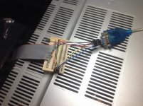
My implementation of a serial breakout box for the Model II:

Serial Breakout.jpg

It is wired per Larry's diagram earlier on, but it isn't working (at 9600 baud, it is still dropping characters, so the handshake is failing).

For reference then, Larry's wiring table (with a bit of reformatting) is:
Code:
Model II
Channel A	    PC DB25	PC DB9
2  TX  ---------->  3 RX  	2 RX
3  RX  <----------  2 TX  	3 TX
4  RTS ---------->  5 CTS 	8 CTS
5  CTS <----------  4 RTS 	7 RTS
6  DSR <--|------- 20 DTR 	4 DTR
8  DCD <--|
7  GND -----------  7 GND 	5 GND
              |-->  8 DCD 	1 DCD
20 DTR -------|-->  6 DSR 	6 DSR

For my wiring, I swapped the table round because I find it easier to wire from DB9 to DB25 (that is, to connect the DB9 end of a connection to the plug first, then locate and connect the other end to the DB25, if that makes sense). Here's my derived table:

Code:
 DB9		 Ch.A
 RX 2 <--------	 2 TX
 TX 3 -------->  3 RX
DTR 4 ------|->	 6 DSR
	    |->  8 DCD
GND 5 ---------	 7 GND
RTS 7 -------->	 5 CTS
CTS 8 <--------	 4 RTS
DCD 1 <-|------ 20 DTR
DSR 6 <-|

The pin numbers are embossed on the connector plugs, so I used those to identify which pin is which. Purple wire is Pin9 (NC).

I have these settings in Windows Command Prompt "mode" command (https://technet.microsoft.com/en-us/library/cc732236(v=ws.10).aspx#BKMK_1)

Code:
Status for device COM5:
-----------------------
    Baud:            9600
    Parity:          None
    Data Bits:       8
    Stop Bits:       1
    Timeout:         ON
    XON/XOFF:        OFF
    CTS handshaking: ON
    DSR handshaking: ON
    DSR sensitivity: OFF
    DTR circuit:     HANDSHAKE
    RTS circuit:     HANDSHAKE

Are these correct? Experimenting with them (blindly, sort of - I can't find a good explanation of what some of the settings really mean) gives no change.

To be honest, I don't understand a lot of what has been put in this thread - I find the theory (DCE vs DTE) a bit confusing. I just want a reliable transfer of data between my PC and the Model II. There must be a way! I cannot easily tell if my PC's USB-Serial port is DCE or DTE. All I know is it is a Prolific PL2303 adapter with a DB9 attached to the end of it, a very dull, mundane and common piece of equipment. The PL2303 datasheet (here) says it supports all the control lines that we have discussed.

EDIT: I checked the wires with a meter, they are all connected perfectly.
 
Last edited:
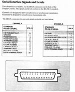
Also, for reference, here is the serial port description from the Model II Operations manual.

Model II Serial description.jpg

It says the A channel is synchronous or asynchronous and I assume that synchronous means "uses receive / transmit clock lines". Since the link is working at the character level I also assume that it is configured for asynchronous operation.

Going back to the CP/M manual:

The computer itself will generate a high on pin 20 (DTR) when it is able to receive a character, and so this can be used to control a device transmitting to a TRS-80 port receiver.

Why not connect the MII's DTR to the PC's CTS?

Edit: Tried, no luck, still dropping characters.
 
Last edited:
What program are you using on the PC side? If you're just using copy con: com1: /b I don't think that expects or uses anything other than software handshake. If you're using a comm program and sending an ASCII file, add some pacing (say 20ms between chars and 50ms at each newline).

See if that helps at all.
 
Back
Top