Holmes
Experienced Member
So I was able to put my RESET button mod together for my PET 2001N. I was anxious to do this mod soon, because when I get my PETdisk, I'll probably be testing tons of programs, and didn't want to have to turn my machine off and on over and over again, subjecting it to repeated power surges.
So I went looking for plans for a RESET switch mod, and didn't find much, so I thought I'd post my solution to this.
I found some plans for a RESET switch in my "PET Personal Computer Guide" by Osborne/Strasma/Strasma. It's a pretty complicated plan they have, so I took out what I wanted. Their plan is basically to wire up a momentary switch, where pressing it one way resets the computer, pressing it the other way activates the NMI (Non-Mask Interrupt) line, which basically sends you straight to the BASIC prompt, but keeps your memory contents intact. They also include plans for a switch to ground the Diagnostic Sense line, which will send the PET into the machine-language monitor on restart (confirmed by dave-m).
At this point, I don't really need the NMI functionality, nor do I need to machine language monitor, so I decided to just do the RESET switch part.
To activate a RESET on a PET, you need to ground PIN 22 on jumper block J4, through a 100-ohm resistor. Pin 22 on J4 is on the left side of the block, and all pins on the right side of J4 are ground pins, so this can be accomplished with a simple 2-position female header connected to a resistor and momentary pushbutton.
With this basic design in hand, I looked at the casing to try to figure out where to put this switch. I didn't want to modify the case at all, so it would have to be accessible from the outside, but I also wanted it fairly hidden. I found the nice wide space on the right side of the lower case, where the memory expansion opening is. I worked it out that I could fit a small button there, and it would be nice and recessed.
So I cut off a 6x2 pin female header block from some old salvaged computer parts, and wired up a 100-ohm resistor, connected to a pushbutton switch, and glued the switch to the side of the header block. You only need to use 2 of the pins, but I figured the larger female header would give more stability. The result was as follows:
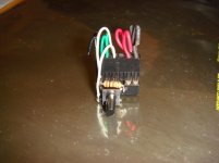
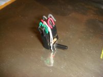
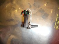 <-- Notice the button is staggered a bit low, so that it's more accessible from the memory expansion opening. If you don't do this, you likely will not be able to reach the button.
I didn't cut off the extra wires, because I wasn't sure if I would need them in the future. That's why it looks like a Medusa head.
Here it is going into place:
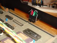
Here it is fully installed from the outside:
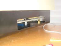
Because the female header block is 6x2, it's pretty stable, and the button is easy to reach by just reaching to the side. And it works great! It's interesting that while you have the button held down, it switches all the text on screen to lower-case, and then when you release the button, it resets.
Anyway, hope this helps someone looking to do something similar. It's a pretty easy mod if you can solder and have the parts, with no permanent changes to the original machine.
So I went looking for plans for a RESET switch mod, and didn't find much, so I thought I'd post my solution to this.
I found some plans for a RESET switch in my "PET Personal Computer Guide" by Osborne/Strasma/Strasma. It's a pretty complicated plan they have, so I took out what I wanted. Their plan is basically to wire up a momentary switch, where pressing it one way resets the computer, pressing it the other way activates the NMI (Non-Mask Interrupt) line, which basically sends you straight to the BASIC prompt, but keeps your memory contents intact. They also include plans for a switch to ground the Diagnostic Sense line, which will send the PET into the machine-language monitor on restart (confirmed by dave-m).
At this point, I don't really need the NMI functionality, nor do I need to machine language monitor, so I decided to just do the RESET switch part.
To activate a RESET on a PET, you need to ground PIN 22 on jumper block J4, through a 100-ohm resistor. Pin 22 on J4 is on the left side of the block, and all pins on the right side of J4 are ground pins, so this can be accomplished with a simple 2-position female header connected to a resistor and momentary pushbutton.
With this basic design in hand, I looked at the casing to try to figure out where to put this switch. I didn't want to modify the case at all, so it would have to be accessible from the outside, but I also wanted it fairly hidden. I found the nice wide space on the right side of the lower case, where the memory expansion opening is. I worked it out that I could fit a small button there, and it would be nice and recessed.
So I cut off a 6x2 pin female header block from some old salvaged computer parts, and wired up a 100-ohm resistor, connected to a pushbutton switch, and glued the switch to the side of the header block. You only need to use 2 of the pins, but I figured the larger female header would give more stability. The result was as follows:


 <-- Notice the button is staggered a bit low, so that it's more accessible from the memory expansion opening. If you don't do this, you likely will not be able to reach the button.
I didn't cut off the extra wires, because I wasn't sure if I would need them in the future. That's why it looks like a Medusa head.
Here it is going into place:

Here it is fully installed from the outside:

Because the female header block is 6x2, it's pretty stable, and the button is easy to reach by just reaching to the side. And it works great! It's interesting that while you have the button held down, it switches all the text on screen to lower-case, and then when you release the button, it resets.
Anyway, hope this helps someone looking to do something similar. It's a pretty easy mod if you can solder and have the parts, with no permanent changes to the original machine.

