• Please review our updated Terms and Rules here

My PET 2001-8 Revival Project

Not a bother at all.

Good to hear it's working. I'm not terribly surprised, mine is the same way. The more I use it, the more it works. If I leave it sit too long, it takes a while to get it going.

Before you go too far with the CRT problem, clean all the pots inside the CRT housing.
 
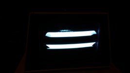
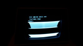
and last time I powered up it was nearly collapsed vertically to a section of horizontal lines. I'll upload a video or pics. Unfortunately I have no experience with HV or analog circuitry. The AC voltage departing the transformer to the monitor was varying from 21-26 but usually around 23-24.

23 VAC is too high. It should be more like 15 VAC. But we know you meter reads high. Don't worry about the video board until we know the vertical and horizontal timing signals are correct. At this point you will need a scope or perhaps a 4 channel USB logic analyzer. Saleae makes a good one for about $100. You might find a cheaper one from China.

We will need to see the screen photos.
 
PET CRT problem

PET CRT problem

Here's some pictures and a video:

20150823_001201.jpg20150823_001203.jpg


The CRT was working ok, just a little blurry before this catastrophic change. Keep in mind I did all my MB troubleshooting with D'Asaro's PET video adapter to an LCD monitor which displayed fine up until I switched over to the PET CRT today. Doesn't that mean that the v/h timing signals are good and the problem most likely lies with the video board? How do we know my meter reads high again? I haven't really posted many readings of it here. I do have a 2 channel digital scope, 50MHz with 1x/10x probes.

Thanks,
Jim
 
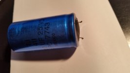
Your CRT unit has bad capacitors. Don't be afraid to change them, but read the instructions here on safely discharging a CRT so you don't have any surprises.

You can verify your meter readings with your scope.
 
Your CRT unit has bad capacitors. Don't be afraid to change them, but read the instructions here on safely discharging a CRT so you don't have any surprises.

You can verify your meter readings with your scope.

Ok. Thanks. Perhaps I'll desolder the biggest electrolytic ones c25: 4700uf, c21: 470uf and c12: 220uf, and c4 (3.3uf at 200v), bring them to the electronics store and test them to see if which if any are actually bad, but just replace all of them with new ones anyway, and if none tested bad, then remove some more and repeat the process.

Jim
 
Oh, I forgot to mention that the brightness pot doesn't seem to do anything even before the screen went wacky. Maybe I'll take that out too. Could be related to the capacitor problems I suppose.
Jim
 
Perhaps, but not likely. It is probably a dead pot (or something else pretty bizarre).
 
It's working!

It's working!

Well, excellent news. I replaced 4 capacitors on the video board and resoldered the brightness pot which had broken free of its solder joints from use over the years and the monitor and brightness pot are working great now! This computer is pretty much fully restored now! I didn't think I had it in me at times.

20150908_225503.jpg
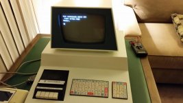
Here's a picture of boot up

20150908_224842.jpg
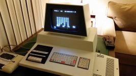
and playing space invaders.

20150908_231655.jpg
The largest capacitor had a noticeable bulge. Perhaps that was the main culprit.

Here's a picture of boot up and playing space invaders. No crashes after a long time running. I loaded a few programs from some old tapes that came with the machine with no problems. It's very satisfying to get to this point. I guess it's the small things that keep me going!

So now I'd like to record some more tapes from my PC (besides Space Invaders) from the archives to try out other software. Now there's a couple of issues left I'd like to solve. Unbelievable, I'm still not fully satisfied, huh?

I have an external data recorder as you can see in the picture. For some reason only this deck can successfully load the tapes I record from my old stereo tape deck from the PC with WinVICE with the record volume set to about +3dB, which is what the old working tapes seem to play back at. The built in data recorder can't read them even when I tried lower and higher record volumes. Furthermore the external data recorder only works when plugged into the internal port for tape 1. It does not work (play or rewind) when plugged in to external tape 2 port. I tried to load something with 'LOAD "",2' and when I pressed play it said searching but the tape wasn't moving. I checked the voltages briefly on the external port and measured +5 on the following pins relative to ground pin 1: B-2, D-4(Read), E-5(write) and F-6(sense), but 0 on C-3 (motor) which is the same on the working tape port 1. Not sure what's going on there. I saw an explanation of how to build a connector so you can record from your PC directly to an external data recorder. Maybe tapes made that way will work with the built in player.

I'm planning to make a reset button to avoid power cycles. There seems to be a few different versions. One is ground the /RES line (on the 2001 it seems to be A27 lower edge to A27 upper edge ground return on the memory expansion port) through a 100 ohm resistor with a push button. Is this a good plan? Maybe I'll just solder the wires and use a very small board to mount the button.
Also I bought a user port connector and plan to wire it up to do the diagnostic mentioned here I already built the wired keyboard connector.

Let me know if you have any suggestions.

Thanks!
Jim
 
Last edited:
Installed Reset switch, Ran ROM Diagnostic with connectors, then no boot again.

Installed Reset switch, Ran ROM Diagnostic with connectors, then no boot again.

Hi,
So I created a reset button by soldering wires to a simple red push button across the capacitor (C7) between pins 1 and 2 of the 555 Reset timer chip. Press it and you engage the reset timer achieving the same behavior as a power on reset. Tested it and it works fine.
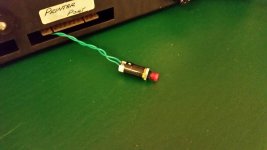
resetbutton.jpg

Next I soldered up a fresh User Port connector with the schematic for the diagnostic connector mentioned in various documents needed to run a self-diagnostic which with BASIC 1 is present in ROM unlike with later versions. At first it didn't work but after looking in The Commodore Pet Revealed I noticed a difference between it and Zimmers document here, namely 5-11 instead of 5-E-11 so I cut the connection to "E". I had already made the keyboard connector. After a few tries I finally got this working! See video
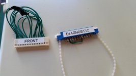
diagnostics.jpg

These diagnostic connector wire ups work for my PET 2001-8 with BASIC-1. You can buy the keyboard connector at an electronics store and the User port connectors are available on EBay and Amazon. See here

User port connector: 2-B, 3-C, 4-D, 5-11, 6-7-8, 9-K, 10-L
Keyboard connector: 1-9-17, 2-10-18, 3-11, 4-12, 5-13, 6-14, 7-15, 8-16, connector key in position 19.

Unfortunately, right after those successes and using the machine for a few hours, it decided to hang in the middle of outputting a large program listing.
This time the display comes up blank and pulling out PIA#1 doesn't affect it nor does waiting any length of time between power cycling. The CPU is getting jammed during an interrupt (probably a BRK), and I suspect that a ROM gave up its ghost (died). I only have one adapter socket, so I could only try one of H3,H4, or H7 at a time which didn't help. I had already ordered a RAM/ROM replacement board from tynemouth which I'll use to hopefully get things working again when it gets here.

Thanks,
Jim
 
I suspect that a ROM gave up its ghost (died). I only have one adapter socket, so I could only try one of H3,H4, or H7 at a time which didn't help. I had already ordered a RAM/ROM replacement board from tynemouth which I'll use to hopefully get things working again when it gets here.

The Tynemouth board should allow for discrimination between a RAM or ROM fault. If ROM, ask owner Dave if there is mapping for enabling of one system main board ROM at a time, but that might not be possible without special PAL decoder.
 
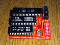
Yes, you can select to enable RAM and ROM separately, and on the 2001 version you can select to enable 8K, 16K or 32K of RAM. I have tried to set it up to allow individual ROMs to be enabled one at a time. The idea was 'replace all but ROM1', 'replace all but ROM2' etc. so you can narrow it down to the culprit, but I can't get that to work.

My GAL equations keep getting cancelled out when I look at the listing it generates. Not sure if it is a problem with the antique wincupl program or if there is something wrong with my equations. Any expert GAL programmers out there? Anyone recommend something better than wincupl to program GAL16V8's? Anyone suggest a modern alternative that works on 5V and is less than 200 pins. The component suppliers pointed me to some Atmel ATF devices, but there didn't seem to be any suitable software or programmers out there, unless I'm missing something.
 
Yes, you can select to enable RAM and ROM separately, and on the 2001 version you can select to enable 8K, 16K or 32K of RAM. I have tried to set it up to allow individual ROMs to be enabled one at a time. The idea was 'replace all but ROM1', 'replace all but ROM2' etc. so you can narrow it down to the culprit, but I can't get that to work.

My GAL equations keep getting cancelled out when I look at the listing it generates.

I assume you exceeded eight product terms in one of the output equations, but I would have thought that Wincupl should have given an error when you assembled the equations.

Using a big CPLD would be overkill for this application. Perhaps an extra Test GAL/PAL that would be temporarily substituted to map in first the CXXX ROM space then, if that passed, erased and and re-programmed for the DXXX ROM, etc. When you find the bad 4K block, you would use an adapter with a 2732 EPROM to replace the two 6540 ROMs.
 
It gives a warning if you exceed the product terms, I've been careful about that, and I'm aware of the limitation of certain pins in certain modes, again it won't compile if I go over the limit there. It just doesn't seem to like the way I'm doing 'this combination of dip switches and this address range or this combination of dip switches and this address range'. It should be the same as I've done for the RAM selection, and that works fine.

I've tried various options for optimisation and demorgan etc. some of which seem to generate output that is wrong, looking at the listing output it generates of what it has done.
 
Thanks to help from Dave M, it looks like the problem is down to the wincupl compiler. Dave converted my code to work on a PAL, and had to remove the address range selection I used in wincupl. Without that, and the address selection written out long hand, it worked. I've rewritten the GAL code to not use the address range selector, or any optimisations in wincupl, and it's now working nicely. The latest batch of boards has also now arrived, so I've sent one off to Jim (in kit form as requested), along with a GAL with the new code in. He should now be able to selectively enable the pairs of ROMs in the 2001 and identify the problem ones.
Commodore PET ROM RAM board.jpg
More info on my blog: http://blog.tynemouthsoftware.co.uk/2015/09/commodore-pet-rom-ram-replacement-boards.html

Thanks,

Dave
 
Resumed revival and got to my goals.

Resumed revival and got to my goals.

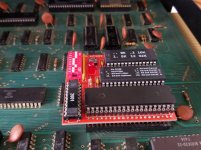
After 2.5 years in storage I finally took out my PET to finish the revival project. It's now working quite well. I surpassed my goal of playing the Basic 2 nice Space Invaders with sound. With the RAM/ROM board I build from a kit purchased from TynemouthSoftware, I can give it up to 32kB and swap in Basic 2 or Basic 4 and use my original RAM/ROM which seem to be good. Really nice. Thanks again, Dave!.
20180303_113502.jpg
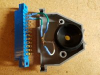
I also built a plug-in sound mod using a piezo buzzer pulled from a small siren (https://www.amazon.com/gp/product/B005DA6BUA/ref=oh_aui_detailpage_o00_s00?ie=UTF8&psc=1) suggested by Holmes here (http://www.vcfed.org/forum/showthread.php?43349-PET-2001-CB2-Sound-Mod). You can even play a crude music keyboard with PetSynth.
20180303_113626.jpg 20180303_220857.jpg
Here it is with me Playing Space Invaders

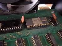
When I got it back out my system wasn't booting because of the unreliable work I did to solder 3 missing pins on the display ROM chip. Should have used an adapter with a new chip, but I guess I'm a sucker for a challenge and impatient for ordering things in the mail. I reseated all the chips except for the display ROM because of its fragile state and got a boot or two briefly which turned into a blank screen. Pushing the board near Display RAM or ROM caused the screen to go crazy. I had to take out that ROM chip and find a better way to deal with the broken pins.

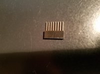
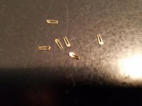
Short of buying another adapter I found a more reliable way to handle the missing pins. I had these small broken pins from inside the broken off 10 way connectors I used in assembling the RAM/ROM board, and they were perfect for sticking in the socket where the missing pins on the chip are. When I put the chip in there they made solid contact and the screen came back to life.
20180303_220344.jpg
(example connector)
20180303_132119.jpg20180303_113515.jpg.

Then I had a weird character issue on the screen issue with changing the character at one screen location affecting another location elsewhere on the screen and changing that one affected a further down location, etc. Long story short, I replaced the 6502 with my original 6502 and problem disappeared.

I was able to record PET software reliably with a volume level of 81 in windows to my tape deck with recording volume set to default and wavprg-4.1 and/or audiotap. D64 editor came in handy to extract a program (prg) file from a disk image (d64) file.

On a personal note this model of computer was the first microcomputer I ever used, and 40 years ago at the age of 10 in 5th grade in Lexington, MA, it kindled a passion for computers and software that led to a career as a software engineer which I am still pursing today. These 8 bit machines were an incredible advancement at the time for all of us. That's why I put in all this effort.

Thanks,
Jim
 
After another 3.5 years of status quo with my 1977 PET 2001-8, I decided to try to make it a lot more usable by doing the following:
  1. Adding fast mass storage with a microSD solution called PETdisk Max by bitfixer.com that plugs into the IEEE-488 port
  2. Upgrade the sound to use an amplified set of PC speakers
  3. Add a Joystick and collect games that support it
I accomplished #2 and #3 by making a new board for the user port and adding a 3.5mm stereo jack for the audio and a DE-9 for the joystick.
One other thing I did was replace the missing PET decal with a quite authentic reproduction, so much so that it doesn't stay on at the corner. The seller has promised to send me one from a new reformulated batch when he gets them. I hope I get a good one because to me it really improves the over all look of the machine.

Part of the inspiration to do these improvements was to best show off the PET at a vintage computer event. I finished in time to bring it to CLASS, the Commodore Los Angeles Super Show which runs 11/6 - 11/7. I will post some pictures of the event here.

I have documented these most recent changes in this video:

PET 2001-8 Playing Games with Joystick and Sound

After this I don't have any more improvement plans. Only thing that I've been thinking about which is available is an external monitor hook up through the user port, but it would have to coexist with my joystick + sound board.

I have to thank youtube vlogger jim_64 who inspired me with his work on a pretty much identical model of PET here:

Stupid Pet Tricks - Turn your 1977 commodore PET 2001 computer into a killa game machine!

Let me know if you like what I've done or have any questions.

Jim
 
Back
Top