• Please review our updated Terms and Rules here

Need some help with 8 inch floppy drive...

Nope--bitrate depends on the encoding (modulation). FM reserves a clock bit for every data bit. MFM is more complex, but is self-clocking.and doesn't use separate clock bits. The raw maximum signal frequency is the same for both.

fm-and-mfm-encoding-write-waveform-for-the-byte-10001111.jpg
 
Nope--bitrate depends on the encoding (modulation). FM reserves a clock bit for every data bit. MFM is more complex, but is self-clocking. The raw maximum frequency is the same for both.
Sorry, what's the "nope" refer to? I thought I understood FM/MFM and bit rate vs. clock rate, but now my head's starting to hurt.

But to get back OT, the question was should the OP indeed always enter 500K for the Data rate in his various experiments?
 
Nope--bitrate depends on the encoding (modulation). FM reserves a clock bit for every data bit.
Not to drag this on longer than necessary, but doesn't FM require two clock bits per data bit (which is why the bit rate is 250K vs. clock rate of 500), whereas with MFM they're more or less the same? Or am I now having a problem with clock "bit" vs. clock "rate"?

As I said, my head's starting to hurt...
 
I find that most folks find the diagram posted above confusing because it traces the magnetization direction and not what's seem on reading. If you look at the write stage of most floppy drives, you'll see that it starts with a "T" type flip-flop.

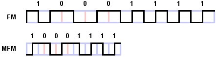
Remember that magnetic recording, with very few exceptions, is a "pulse" technology on the read side. So, in the above diagram, every time the magnetization "flips", the read circuitry will see a pulse. Let's reproduce the diagram again:

fm-and-mfm-encoding-write-waveform-for-the-byte-10001111.jpg


Armed the information that we see a pulse occurs every time the magnetization changes direction, so let's write a "1" for every clock interval with a pulse and a "0" if there is none.

So for the FM trace we have : 11 10 10 10 11 11 11 11 - note that every data bit is prefixed by a "1" clock bit.

MFM encoding is a bit more involved, as it depends on history of what was recorded--you can't have more than 2 successive cells with no transition/pulses. Further pulses can occur on half-clockimes, but no pulse can ever be closer from the previous one than a whole clock period. A "1" bit is signified by a transition on a half-clock; a transition on a full-clockl boundary and signifies a data clock bit.

You can see that FM has a spectrum with two peaks: t and 2t (for 1 and 0 cells) and MFM has a spectrum of 1, 1.5 and 2t components. The bandpass frequencies are still the same and you can see where MFM might be a bit more susceptible to timing "jitter", which is why most MFM data separators are PLL (or the digital equivalent) stabilized.

I've tried to be as brief as possible and hope I haven't over-simplified things to the point of error.
 
I get all that; As I said I'm just confused by your "FM reserves a clock bit for every data bit" when it seems to me that every FM data bit requires two clock bits, and the ambiguity that while "data transfer" rate generally refers to bit rate apparently "data" rate usually refers to clock rate.

But confusion is more and more my normal state these days... ;-)

Anyway, interesting as it is, other than whether the OP should enter 500 or 250 at the data rate prompt this is getting a little off topic...

m
 
He should use 500Khz as the clock rate.

Don't confuse FM with the NRZ used in, say, async comms. Very different animals. FM always has (with certain "flagging" exceptions) a 1 clock bit followed by a 1 or 0 data bit. Got it? 2 bits, one of which is always 1; the other may be 1 or 0 depending on the data being sent. Clock bits have no intrinsic information content. MFM introduces clock bits only as needed to maintain synchronization.
Let's hope the OP read that among all the other rambling... ;-)

Still sounds like 2 clock bits per FM data bit to me, so I still don't get what you meant by "FM reserves a clock bit for every data bit;" but that's OK; I'm sure folks are getting bored by now...

And of course baud & bps are different animals from FM clock &. bit rates, I just meant that it's another example where the bit rate is not necessarily the same as the "clock" rate.

m
 
Last edited:
Let me try again by saying this: Clock period is not the same as bit cell. At a 500KHz clock a bit cell (4 usec) in FM is 2 clock periods; it however encodes only one explicit clock bit per bit cell. It results in a data rate of 1 bit per bit cell, or 250Kbits/second. In MFM, by dint of clocking either on the edge or the middle of a clock period, a bit cell is 2 usec and results in a data rate of 500K bits/second. In MFM, clock bits (i.e. nondata transitions) are supplied only as needed to maintain good synchronization. They always occur on the edge of a clock period.

I think what you're trying to say is that you see FM as requiring two clock periods/cycles. That's true--but you have to differentiate the notion of "data" (i.e. information bits) and "clocks" (non-information bits intended for synchronization).

Communications protocols such as asynchronous rely on the fact that the implied clock domain is the same on both the talker and listener side--and, aside from small errors, is essentially the same and need only be accurate over the period of a single character, so including explicit clocking information would be superfluous. Note that synchronous communication requires a separate clock signal.
 
What Al says is correct--don't confuse the clock rate with the bitrate. All 8" diskettes are written at 500KHz clock (high density), whether they're FM or MFM (or MMFM, but that's a different subject). The bitrate of FM is half that of MFM, but the clock is the same.

What are you using for a floppy controller? Has it passed the FM test of TestFDC{/url]?


I use an old ISA controller, which works with a 360K 5.25 inch floppy. There should be no problems with writing a single density media. By the way, testfdc is not usable with an 8 inch drive anyway, since it tries to format 80 cylinders instead of 77, and, of course, fails for both - single and double density formats...
 
AFAIK, there are no non-ISA legacy PC controllers, even if they're embedded into a non-ISA board chipset; the DMA and interrupt structure remains a child of the ISA bus scheme (IRQ 6, DMA 2, Port 3F2-3f7).

However, you'll need to use a controller that's capable of driving 1.44MB 3.5" floppies--an old one-data-rate 360K controller won't pass muster. You need to use a controller that's capable of 500KHz "high-density" operation. (500KHz applies to both high density 1.2M (5.25') and 1.44M (3.5") drives). I'm not suggesting that you drive your 8" drive with testfdc--but rather hook up a 3.5" or 5.25" high-density drive and run the test. If it passes for both FM and MFM high-density data rates, then you're good.

Did a test - is it really that bad as it looks? Basically, it looks that my floppy controller is not capable of writing any of the formats I need:

P1001380.jpg

I had another PC with a floppy controller - this time Celeron 2.8 - the results does not seem to look better anyway...

P1001378.jpg

Meanwhile my 5V adapter for feeding 8 inch drive gave up ghost - IC circuit exploded (I strongly suspect this was manufacturing fault), so I need a new one.

Now I need a compatible floppy controller for writing 8 inch floppies. I will make a research, but are there any known models, which work? That would be better rather than getting all possible floppy drive controllers/computers with controller.
 
...
Now I need a compatible floppy controller for writing 8 inch floppies. I will make a research, but are there any known models, which work? That would be better rather than getting all possible floppy drive controllers/computers with controller.
Check out the registry at Dave Dunfield's site referenced in post #2
http://classiccmp.org/dunfield/img/index.htm

Is your controller 8-bit or 16-bit ISA?
 
Last edited:
...I think what you're trying to say is that you see FM as requiring two clock periods/cycles. That's true--but you have to differentiate the notion of "data" (i.e. information bits) and "clocks" (non-information bits intended for synchronization).
Yup; that's what I was trying to say; no need to reiterate that bit and clock rates are not the same thing, that's obvious.

We've gone off on a discussion of diskette and comm protocols (mostly talking past each other somehow); I only wanted to clarify Al's ambiguous remark that "8" disks always write at 500K"; most references to "data rate" out there refer to bps (250Kbps for 8"FM) whereas Al is obviously talking about clock rate (500KHz).

The relevance to this thread was what the OP should enter in response to IMD's Data rate question; apparently it should actually be the clock rate.

e.g. (From Patterson's blog)
Those 5” disks would spin at 300 RPM (5 revolutions per second), a little slower than the 360 RPM (6 revolutions per second) of 8” disks. And the 5” disks had exactly half the data rate, 125,000 bits per second, vs. 250 kbps for 8”.

Also Wikipedia:
https://en.wikipedia.org/wiki/List_of_floppy_disk_formats
 
Last edited:
Mike, it's worse than that--when I talk about clock bits, I'm talking about an actual recovered clock from the data stream. This gets to be important when talking about address marks with "missing" clock bits.

Yes, there's data rate and clock rate. Perhaps the best way to talk about them is "bit cell time". It can get to be really confusing if you talk about the high-end spectrum. Both MFM and FM have the same high frequency limit in their spectrum; but the encoding efficiency differs. Given the "dumbness" of diskette drives, it's the bandpass that's probably of most interest to an engineer; whether FM, MFM, MMFM, GCR or RLL encodings are used doesn't really matter for him.
----------------------------
@Adventurer, your FDCTEST results show why you're not having luck.

If you're looking for 486-P3 integrated FDC motherboards, support of FM (single density) is hit or miss. For example, I have an FIC KC19 (Intel 820) P3 motherboard, that has great support for FM floppies, but it stands as an island in a sea of similar (including 440BX) motherboards with no support at all for FM. Unfortunately, support for ISA slot (it has 2) DMA is completely absent.

The ISA FDC controller done here by James Pierce and others does support FM.
 
Last edited:
Check out the registry at Dave Dunfield's site referenced in post #2
http://classiccmp.org/dunfield/img/index.htm

Is your controller 8-bit or 16-bit ISA?

Thanks, I did not pay attention at the beginning. It seems that FD controller is no less important than FDAP adapter or the 8 inch drive itself.

I do think it is 16 bit adapter, but I am not sure. One thing I know - I need another one :)
 
Find yourself a 16-bit ISA SCSI controller with FDC. Look at the FDC chip--if it's by NSC, you're in luck. Other possibilities exist, however.

Don Maslin and I started compiling a list years ago--I suspect that Dave's list is derived from that.
 
Thanks to Modem7, today I finally received Textpack 4 floppy for IBM Displaywriter. It works! However, it is really frustrating to wait 6 minutes for it to boot, with long gaps of complete silence, with floppy drive being idle.
P1001386.jpg

Unfortunately, I can not make a backup copy of it, because Displaywriter notices a read error and aborts the operation. Is there a setting somewhere to ignore read errors? I did not find one...

With the Displaywriter floppy being in DS/DD format, it makes it compatible even with my current floppy controller, however, because of read errors on track 5 and 6, all I'm getting is unusable image, because ImageDisks no longer "understands" the format of the floppy, and writes nothing after track 6

Tried Teledisk with similar results - the only difference is that Teledisk stops writing after track 7. Is there a remedy to this problem, or the floppy has to be with 0 read errors?

Slowly starting to think about ordering Kryoflux USB controller...
 
Back
Top