• Please review our updated Terms and Rules here

Neglected PET needing some love

Yep, plug compatible on the PET - no adapters required.

Plug 'n play...

Dave
nice thanks. I'll order some.

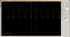
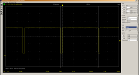
Got the hantek today. been pretty busy with work but I did have a second to check it out and get that open source program working on it. Here's my measurements:

Vertical:
1665174193683.png

Horizontal:
1665174228717.png

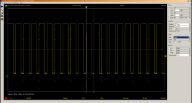
Another shot of Horizontal measuring the ON time instead of the OFF time:
1665174299802.png
 
Actually, you need to measure from leading edge to leading edge (or falling edge to falling edge) not the width of the low or high bit of the signal in order to calculate the frequency.

We can work it out for the H signal (by summing the two delta times together) but can't do this for the V signal (I don't think).

Dave
 
Agree, the H looks OK but we cannot tell with the V until we see a full cycle, but if that is frequency information on the bottom right, it says 100 Hz which is not correct. Hopefully it should measure 60 Hz and a period of 16.66 mS.
 
As dave_m noted the scope software appears to indicate the frequency of the signal (in the bottom right hand corner in this case) along with many other properties, but if Divarin can measure the leading edge to leading edge time (a) between two consecutive pulses of the V-Drive signal and (b) between two consecutive pulses of the H-Drive signal so we can work the frequencies out 'manually' that will give us some reassurance that the frequency being shown at the lower right corner is indeed the frequency of the signal being monitored.

For further assurance you could also put the scope probe on some point where the frequency is already known, such as the main system clock, and see what the frequency indicated in the lower right corner is then.
 
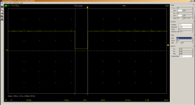
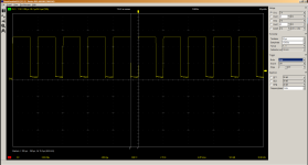
Okay here's the vertical: 60hz1665232496675.png


And the horizonal: 20khz
1665232595025.png

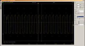
As for the clock, I tried taking this from pin 37 of the CPU based on this schematic: 1 mhz:
(If that was the wrong place, let me know)
1665232947548.png
 
Those signals look fine. The CRTC is being properly initialized.
Okay so that means what I'm seeing on my screen (through the RGB2HDMI) isn't because the RGB2HDMI is struggling to make sense of an invalid signal but because the computer itself is not behaving correctly. I guess I'll have to wait until my 2716 eproms come in to try the pettester rom.
 
...the RGB2HDMI is struggling to make sense of an invalid signal but because the computer itself is not behaving correctly.

Not too sure about that - as dave_m said it looks as though the CRTC is being properly initialised and the V-Drive and H-Drive signal frequencies are what they are expected to be. Resolving that question has been an almost immediate benefit of buying your new scope.

It's now sounding to me more like an RGB2HDMI configuration (or other) problem, but I don't have enough experience with those to be sure, so will defer. There is one other thing you could try, if you have not already, to get the RGB2HDMI adaptor working - PETs usually have links near the video, V-Drive and H-Drive signal circuit - these are used to define whether their related signals are 'normal' or 'inverted' and they are provided because some of the monitors supplied by Commdore needed one or more of the signals to be inverted. So- connect up the RGB2HDMI again and try moving the inversion links for the H-Drive and V-Drive signals one at a time. If doing so has no beneficial effect, return them to their original settings.

Would you consider trying to build one of the simple dedicated PET to Composite converter circuits referred to earlier in the thread? I don't know what you have in the way of construction experience or parts.
 
Last edited:
That is the purpose of the +V, -V, +H and -H settings in the video adapter - it sets the drive signal expected to the inverse sense.

It doesn't hurt to try though. Just remember to note down what the current settings are and put them back as you found them if it doesn't work.

Dave
 
Would you consider trying to build one of the simple dedicated PET to Composite converter circuits referred to earlier in the thread?
Our Op has a HDMI Monitor.
Of course the RBG-HDMI board has an option for composite input. Is that what you mean?
His RGB board works with a C128 which I think is IBM PC CGA compatible so separate syncs should work. I am at a loss...
 
No, I meant that historically speaking, of the different types of monitors supplied and fitted by Commodore, some needed the signals the 'normal' way up and some needed them inverted. That is why the links are provided, and they would normally be set to match the fitted monitor before the machine left the factory and never moved again.

I'm suggesting that maybe the RGB2HDMI gadget is expecting active-high Vsync or active-high Hsync, whereas the machine is currently configured to output active-low V-Drive and active-low H-Drive signals, so it might be worth temporarily moving those links one at a time to see if that improves things. If not - as Daver2 said - they should be set back to their original positions.
 
Divarin,
Here is the settings I use for the Commodore 8032 if you care to try this profile on the RGB board. Copy and Save as a text file 'aaa 8032' so it will be the first profile on the list. Put this file in the Profile directory(SD chip) and then Select it from the Profile menu. It has a few different values from Chuck's profile. Of course it sounds like you have already tried every setting. Make sure you hit the Reset button (sw4) if it doesn't sync in right away.
Make sure you have already saved whatever profile you want as the default configuration to go back to on next power up.

sampling2=6,6,6,6,6,6,6,0,1,0,4,0,0,0,0,0,0,0,0,0,100,256,100,256,100,256,256,256
geometry2=152,26,480,256,576,288,3,4,1,0,12000000,768,5000,312,4,0,2
sampling=3,3,3,3,3,3,3,0,1,0,7,0,0,0,2,0,0,0,0,0,100,256,100,256,100,256,256,256
geometry=68,47,640,200,800,270,1,2,0,1,16000000,800,5000,333,0,3,0
auto_switch=2
palette_control=1
scanline_level=0
It looks like I'm getting the same results from your profile that I got from mine.

Not too sure about that - as dave_m said it looks as though the CRTC is being properly initialised and the V-Drive and H-Drive signal frequencies are what they are expected to be. Resolving that question has been an almost immediate benefit of buying your new scope.

It's now sounding to me more like an RGB2HDMI configuration (or other) problem, but I don't have enough experience with those to be sure, so will defer. There is one other thing you could try, if you have not already, to get the RGB2HDMI adaptor working - PETs usually have links near the video, V-Drive and H-Drive signal circuit - these are used to define whether their related signals are 'normal' or 'inverted' and they are provided because some of the monitors supplied by Commdore needed one or more of the signals to be inverted. So- connect up the RGB2HDMI again and try moving the inversion links for the H-Drive and V-Drive signals one at a time. If doing so has no beneficial effect, return them to their original settings.

Would you consider trying to build one of the simple dedicated PET to Composite converter circuits referred to earlier in the thread? I don't know what you have in the way of construction experience or parts.

I'm not sure where these links would be on this board.

I'll take a look at the composite converter circuits and see it they seem like something I can do or not.

Edit: while googling about this I found this post from you dave_m. Since mine is also the 8032 I tried plugging in the keyboard and trying the off/rvs key but no change was noticed.
 
Last edited:
It looks like I'm getting the same results from your profile that I got from mine.
ah, too bad...and no effect with the Reset button? With my RGB board, it will power up working but the characters were a little fuzzy but when I hit the Reset, it locked in with high resolution.

I suppose you might have a slightly corrupted program in your CPLD chip, but I have no idea about reloading it.
Well hopefully you can get your PET monitor working now that you know you have good timing signals to it, and now have a working scope.
 
I know Adrian Black got his PET working with an RGBtoHDMI, and I just had a look at his profiles, and they differ to dave_m profile. Have a look at his github profile for a couple of different options.

Puth them in a txt file like you did with dave_m, and see if it's any different.

It might also be worth double checking the cable you are using.
 
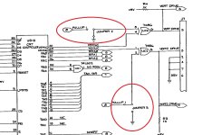
This is the circuit location of the jumpers which determine whether the V-Drive and H-Drive signals coming out of your mainboard are 'normal' or inverted. I don't know if these will be soldered links or PC-style movable plug-in jumpers on three pin headers. It looks like they are Jumper 2 and Jumper 3 respectively.8032_Hdrive_Vdrive_Inversion_Jumpers.jpg
 
I know Adrian Black got his PET working with an RGBtoHDMI, and I just had a look at his profiles, and they differ to dave_m profile. Have a look at his github profile for a couple of different options.

Puth them in a txt file like you did with dave_m, and see if it's any different.

It might also be worth double checking the cable you are using.
Wow, those are different numbers. Of course they are for the 40 column 4032. I think our OP has an 8032. But heck, he should try it. Nothing else has worked.
 
Actually the characters are perfectly clear, as far as i can tell I'm seeing an entirely clean and valid video signal.

It's just random garbage characters.

The first few power-ups it looked like the pixels of each character was random and shifting but as it stayed on longer that sort of resolved itself (see the video I posted earlier)

Now I can clearly see that each character is a valid petscii character.

It's as if you wrote a program to print random characters on the screen and loop forever, which is why I'm more suspicious of the rom(s)
 
Back
Top