Upcoming Events:
| VCF West | Aug 01 - 02 2025, | CHM, Mountain View, CA |
| VCF Midwest | Sep 13 - 14 2025, | Schaumburg, IL |
| VCF Montreal | Jan 24 - 25, 2026, | RMC Saint Jean, Montreal, Canada |
| VCF SoCal | Feb 14 - 15, 2026, | Hotel Fera, Orange CA |
| VCF Southwest | May 29 - 31, 2026, | Westin Dallas Fort Worth Airport |
| VCF Southeast | June, 2026 | Atlanta, GA |
-
Please review our updated Terms and Rules here
You are using an out of date browser. It may not display this or other websites correctly.
You should upgrade or use an alternative browser.
You should upgrade or use an alternative browser.
New, to me DEC PDP8E
- Thread starter Mike_Z
- Start date
Mike_Z
Veteran Member
I ran an initial load test on the +5, +15 and -15 volt supplies. Here is what I found;
+5
Current Voltage
0 Amp 5.30 volts
1.6 5.20
2.7 5.15
9.6 4.73
-15
Current Voltage
0 Amp 14.58 volts
1.5 14.49
2.8 14.41
4.8 13.90
6.2 13.73
+15
Current Voltage
0 mA 14.81 volts
400 14.76
800 14.72
I ran each level for 10 minutes and these are the final numbers. I then adjusted the voltages. The +5 was too high.
+5 adjusted
Current Voltage
0 Amp 5.09 volts
9.7 4.90
The + and - 15 volts were adjusted together
-15 adjusted
Current Voltage
0 Amp -14.82 volts
6.2 -14.67
+15 adjusted
Current Voltage
0 mA 15.05 volts
800 15.00
I've got all three voltages loaded up and ran for an hour. There is a slight increase in fan exhaust temperature. Started at 75°F, after 20 minutes it was up to 83.5°F, after 40 minutes, 88.8°F and at an hour, 89.2°F. The pass transistors heat sink were warmer than the diode heat sink.
Looks good. Now I have to wait for parts to continue with the front panel control board. Mike
Very good, great progress!
The 5v regulation on the first run was terrible (0.6v drop at 10A or so!) but the second run was better (though still a little more of a drop than I'd have expected). The -15 regulation was very poor too, but much better second time. It shouldn't really have changed much - just tracked the nominal setting. Were you measuring them after a longish wiring run? When I measured mine it was more in the region of tens of mV regulation. I'd maybe measure again (right at the output) in case there's a high resistance or poor joint somewhere.
The 5v regulation on the first run was terrible (0.6v drop at 10A or so!) but the second run was better (though still a little more of a drop than I'd have expected). The -15 regulation was very poor too, but much better second time. It shouldn't really have changed much - just tracked the nominal setting. Were you measuring them after a longish wiring run? When I measured mine it was more in the region of tens of mV regulation. I'd maybe measure again (right at the output) in case there's a high resistance or poor joint somewhere.
Last edited:
Mike_Z
Veteran Member
You may be correct. I was using loose parts and alligator clips. Between runs I removed the regulator cards, cleaned the contacts and sockets some and seated the boards a couple of times. This could have been the problem. Thanks Mike
m_thompson
Veteran Member
The +5V regulator is painful to debug because it usually trips the crowbar which blows the +5V fuse. You are pretty lucky to have everything work OK.
I usually lift the gate wire to the crowbar SCR when troubleshooting for that very reason.The +5V regulator is painful to debug because it usually trips the crowbar which blows the +5V fuse. You are pretty lucky to have everything work OK.
Just make sure you don't have real boards as the load!
DDS
Veteran Member
The +5V regulator is painful to debug because it usually trips the crowbar which blows the +5V fuse. You are pretty lucky to have everything work OK.
I'm not sure if it would work in this context or if in fact it could make things worse, but we used to replace a fuse temporarily with a "resistance lamp" for trouble shooting purposes. If you were drawing enough current to blow a fuse the lamp would light but would also act to limit the current much like when using a light bulb to form a capacitor. It saved us from accumulating a large pile of blown fuses while finding a short and was critical if fuses were in short supply. But "crowbar" circuits were rare in the parts of the telephone switches I mostly worked on. So in this case the trick might prove worse than useless.
Marty
Veteran Member
Hi All;
DDS, I hadn't thought of that, but it makes sense..
Did You still have Grasshopper fuses in the equipment that You serviced, and were/are they resettable or were they like other fuses once blown their gone ??
THANK YOU Marty
DDS, I hadn't thought of that, but it makes sense..
Did You still have Grasshopper fuses in the equipment that You serviced, and were/are they resettable or were they like other fuses once blown their gone ??
THANK YOU Marty
I usually lift the gate wire to the crowbar SCR when troubleshooting for that very reason.
Yes, me too. You find crowbars on all sorts of supplies. Just a momentary disconnection somewhere or a careless short with a probe and off it goes. Not so bad with a re-entrant current limit but bad news with a fuse.
DDS
Veteran Member
Hi All;
DDS, I hadn't thought of that, but it makes sense..
Did You still have Grasshopper fuses in the equipment that You serviced, and were/are they resettable or were they like other fuses once blown their gone ??
THANK YOU Marty
The old electro-mechanical switches (SXS, Panel and Crossbar) had whole bays (PRTD -- Power Ringing and Tone Distribution) full of the old type 35 "grasshopper" fuses. When the fuse element blew it released an indicator spring that contacted an alarm bus bar which alerted people to the trouble condition. When I started in 1971 these were already being phased out by type 70 fuses. The type 70 looks something like a common glass buss fuse but adds a spring loaded cap/indicator on one end. When this type blows the spring is released pushing the fuse cap outwards against the holder bringing in an alarm and allowing the indicator to protrude through the holder's cap. Still newer equipment is being installed that replace the type 70 fuse with the grandchild of the type 35. These are the small push-in square fuses that are becoming common in cars.
Both the type 35 and the type 70 lent themselves to the addition of a resistance lamp in place of the blown fuse element to perform the trick I mentioned above. The type 70 worked really well because the wires to the lamp could be passed through the holder's indicator hole leaving the lamp in plain sight at the bottom of the bay.
As far as a resettable fuse and/or circuit breaker goes, some newer equipment had breakers for the bay, but individual circuits in the bay always used one-time fuses. Older equipment had fuses only.
Mike_Z
Veteran Member
Just got back from a few weeks of enjoyment in the North Woods of Wisconsin. Spent a lot of time in the woods near Lakes Scott and Shelp in the Nicolette Forest. It was one of those 'get your head on straight' relief vacations.
Anyway I have the power supply in shape and back in the pan with the 20 slot Omnibus. I made new cables between the power supply and the Omnibus.
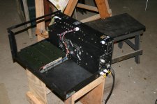
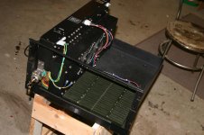
The next thing was to plug in the front panel board. Well, it immediately popped the 15 volt fuse. Turned out that one of the 6.8uf capacitors was shorted. So I replaced all of them on this board. The next attempt showed all the lamps lit. With this behind me, I brought the address bus omnibus pins high and each address light would go out. I wanted to test the other items, but that really requires a lot of jumpers. So I decided to clean up the timing generator board and plug that one in. No smoke and the fuses were still good. I then spent some time cleaning up the basic computer boards and plugging them in one at a time, testing for smoke and failure. No problems until I plugged in the bus loads. Again it was a 6.8uf capacitor. They were all replaced. I ordered a bunch more and probably should go through all the other boards and replace those also. After getting all the boards in place and having no apparent failures, I tried the switches. I could change bits with all the switches except switch zero and one. Tackling zero first I found another open trace. So I added a jumper around the open. With the Front Panel board back in the bus, I wanted to check if my repair worked. I turned on the computer and it light up for about 8 seconds and then everything blacked out except the fans. All the power supply voltages were zero. My heart sank, I figured that the main transformer had a problem. After some checking, I was right the primary winding was open. RATS! After thinking about for a while I decided to remove the transformer and see if the problem could be fixed. There are a lot of connections and taps on this transformer. The primary winding connections are buried on the inside requiring it to be removed. An hour or so later, I got it out and measured the resistance between the hot and the neutral, infinite resistance. Just of grins I tried the 240 volt connections and it worked. Hope comes back. I cut into the transformer and found that the 120 volt tap was brought out and wrapped around the terminal. It was soldered, but only to itself. Apparently for the last 40 years there was contact here, but when I got it, it decided to open up.
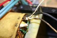
In this picture you can barely see the tap and the neutral winding to the terminal. I pulled the tap out and reapplied it to the terminal. It took another 2-3 hours to re route, terminate and tie up all the wires. But it was worth it, all is right with the power supply again. Now back to the testing.
Mike
Anyway I have the power supply in shape and back in the pan with the 20 slot Omnibus. I made new cables between the power supply and the Omnibus.


The next thing was to plug in the front panel board. Well, it immediately popped the 15 volt fuse. Turned out that one of the 6.8uf capacitors was shorted. So I replaced all of them on this board. The next attempt showed all the lamps lit. With this behind me, I brought the address bus omnibus pins high and each address light would go out. I wanted to test the other items, but that really requires a lot of jumpers. So I decided to clean up the timing generator board and plug that one in. No smoke and the fuses were still good. I then spent some time cleaning up the basic computer boards and plugging them in one at a time, testing for smoke and failure. No problems until I plugged in the bus loads. Again it was a 6.8uf capacitor. They were all replaced. I ordered a bunch more and probably should go through all the other boards and replace those also. After getting all the boards in place and having no apparent failures, I tried the switches. I could change bits with all the switches except switch zero and one. Tackling zero first I found another open trace. So I added a jumper around the open. With the Front Panel board back in the bus, I wanted to check if my repair worked. I turned on the computer and it light up for about 8 seconds and then everything blacked out except the fans. All the power supply voltages were zero. My heart sank, I figured that the main transformer had a problem. After some checking, I was right the primary winding was open. RATS! After thinking about for a while I decided to remove the transformer and see if the problem could be fixed. There are a lot of connections and taps on this transformer. The primary winding connections are buried on the inside requiring it to be removed. An hour or so later, I got it out and measured the resistance between the hot and the neutral, infinite resistance. Just of grins I tried the 240 volt connections and it worked. Hope comes back. I cut into the transformer and found that the 120 volt tap was brought out and wrapped around the terminal. It was soldered, but only to itself. Apparently for the last 40 years there was contact here, but when I got it, it decided to open up.

In this picture you can barely see the tap and the neutral winding to the terminal. I pulled the tap out and reapplied it to the terminal. It took another 2-3 hours to re route, terminate and tie up all the wires. But it was worth it, all is right with the power supply again. Now back to the testing.
Mike
Marty
Veteran Member
Hi All;
Mike, all I can say is WOW!!!!!!!!!!
Great Job...
THANK YOU Marty
Mike, all I can say is WOW!!!!!!!!!!
Great Job...
THANK YOU Marty
billdeg
Technician
Inspiring results.
DDS
Veteran Member
Threads like this are why I come to this site.
Mike_Z
Veteran Member
Could have been. The power cord was replaced in a rather cheap way. The cord is held in place on the case with a Romex connector and the wire was spliced in with butt splices. Obviously not DEC. Although I didn't see any evidence of a connection to the #3 terminal of the power transformer. Being in a machine shop it could have been 240 rather than 120, who knows.
Mike
Mike
Mike_Z
Veteran Member
While I'm waiting for some more parts to arrive in the mail, I started to look at some of the functions in this machine. One item that I'm a little confused with is the POWER OK. There is a simple circuit in the power supply that provides this signal. Looks like, if POWER OK is truly OK this level is a positive voltage, whereas if either the +5 or 15 voltage supplies fail the POWER OK is ground. This signal controls the RUN Flip/Flop and thus the shift register on the Timing Generator card, stopping the timing signals.
This seems straight forward, but then I have a M848 Power Fail and Auto Restart card. This card appears to load a predetermined address on power up and then starts the computer. This circuit monitors 28 Vac off the main power transformer. I think I understand the auto restart, but what is the Power Fail portion of this? Does it just get the auto restart ready when the power comes back? Or, does it do more like the POWER OK, but I don't see any STOP signals etal.
Since I don't have any ROM in the machine should I just disable the M848 with the en/disable switch or just run without the board?
This is my first experience with any DEC equipment, by the way I'm really struggling with this negative logic.
Thanks, Mike
Marty
Veteran Member
Hi All;
Mike, I don't know for sure,
But, If it is like the PDP 11/45, the the Auto-Restart will save the Registers to somewhere in Core, and Then When Power comes Back it Loads that information back into the Registers, and Run the program that was in Memory..
THANK YOU Marty
Mike, I don't know for sure,
But, If it is like the PDP 11/45, the the Auto-Restart will save the Registers to somewhere in Core, and Then When Power comes Back it Loads that information back into the Registers, and Run the program that was in Memory..
THANK YOU Marty
From back in my TTL days negative logic was often preferred because of the strong driving direction and convenience of a wired-NOR. Simple gates always invert and I find myself thinking automatically in NAND and NOR terms.
What drives me absolutely nuts though is the regular interchanging on DEC's schematics of NAND and NOR symbols with OR and AND symbols with inverted inputs - I just don't think that way.
What drives me absolutely nuts though is the regular interchanging on DEC's schematics of NAND and NOR symbols with OR and AND symbols with inverted inputs - I just don't think that way.
Mike_Z
Veteran Member
I'm still recovering from turkey overdose, but, not so that I can't even think about this stuff. Marty, I don't think my M848, Auto ReStart is that sophisticated. Looks to me that there is a power up and a power failed detector. I think that the power up circuit will load a selectable address (jumpers) and then restart at that address. I'm still confused as to how the power fail works. When I get more time I'll try and figure it out. For now, I'm going to leave this board out of the machine, so as not to complicate the initial startup.
Bob, this negative logic is confusing, at least at this time, to me. I'm not sure, exactly, how to go at it. I was brought up on positive logic, one's and zero's, associated with +5v and 0v. I could just look at a gate and see what was what. I'm not sure why the negative logic should be a problem, maybe sometimes, I'm thinking in terms of voltages rather than 1's an 0's. One question I have is, does the DEC schematics use negative logic gate symbols? For example, a positive AND gate is the same as a negative OR gate with NOT's on the inputs and outputs. The DEC prints have many of these NOT's, but sometimes you will see a normal (looking) NAND gate. Suppose, that over time will get this straight.
I was looking at my memory cards for this machine. I have two, three card modules of 8k x 12 core memory cards. I was wondering how these cards are set for the EMA addresses. Inspection shows that there are a couple jumpers on each card. There are three EMA jumpers, EMA0, EMA1 and EMA2. One of my memory cards have all three jumpered and the other has the middle one (EMA1) cut. The three bits make sense for 4k memory (8x4k=32k), but these are 8k boards.
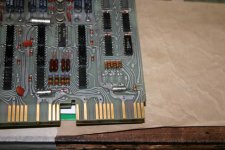
Then there are jumpers labeled SLA and SLB. Could these make up the 8k difference?
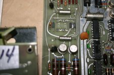
Anyway, I'm wondering about these jumpers.
Still recovering, maybe another drumstick would help. Mike
Bob, this negative logic is confusing, at least at this time, to me. I'm not sure, exactly, how to go at it. I was brought up on positive logic, one's and zero's, associated with +5v and 0v. I could just look at a gate and see what was what. I'm not sure why the negative logic should be a problem, maybe sometimes, I'm thinking in terms of voltages rather than 1's an 0's. One question I have is, does the DEC schematics use negative logic gate symbols? For example, a positive AND gate is the same as a negative OR gate with NOT's on the inputs and outputs. The DEC prints have many of these NOT's, but sometimes you will see a normal (looking) NAND gate. Suppose, that over time will get this straight.
I was looking at my memory cards for this machine. I have two, three card modules of 8k x 12 core memory cards. I was wondering how these cards are set for the EMA addresses. Inspection shows that there are a couple jumpers on each card. There are three EMA jumpers, EMA0, EMA1 and EMA2. One of my memory cards have all three jumpered and the other has the middle one (EMA1) cut. The three bits make sense for 4k memory (8x4k=32k), but these are 8k boards.

Then there are jumpers labeled SLA and SLB. Could these make up the 8k difference?

Anyway, I'm wondering about these jumpers.
Still recovering, maybe another drumstick would help. Mike
