• Please review our updated Terms and Rules here

Olivetti M24 / AT&T 6300 Keyboard Emulator

The S1, S2 .... key board is most likely a carry over from the Olivetti M20 that came before the M24 was designed. One might look at the M20 users manual for what those keys did for the M20. They are most likely for the same purposes as the M20.
Dwight
 
Great work Valerio. This will be a great help to get my PC 6300 functional. A couple questions: I already have some 2N2222's, would I connect Emitter to ground, Base to the Arduino and Collector to the respective M24 and AT keyboard connections? Your schematic shows Arduino pins D9, D10, D11, and D13 connecting to ground via DIP switches, is this required or for future use?
 
Great work Valerio. This will be a great help to get my PC 6300 functional. A couple questions: I already have some 2N2222's, would I connect Emitter to ground, Base to the Arduino and Collector to the respective M24 and AT keyboard connections? Your schematic shows Arduino pins D9, D10, D11, and D13 connecting to ground via DIP switches, is this required or for future use?

Thanks. As for using 2N2222s, yes what you write is correct, although pls do put a resistor between the Arduino pin and the transistor base to limit the base current - I think I used 10kOhm but the exact value is not terribly important (I'm guessing anything between 1k and 50k would probably work). The DIP switches are not required with the current version of the software. I am thinking of using them in future versions to make simple configuration changes - like turn USB debug information ON/OFF, or turn keyboard emulation via USB tty ON/OFF - other suggestions welcome.
 
Actually one important note - if you use 2N2222s, the software must be edited as the logic levels on the Arduino output pins would have the opposite effect. With the 74LS07 (which is a non-inverting OC buffer) a low level on the Arduino pin causes the M24 / AT lines to be brought LOW. If you use 2N2222s, you need a HIGH level on the Arduino pin to bring the M24 / AT lines LOW - the exact opposite behaviour, equivalent to using inverting buffers. Since the software is written to use a 74LS07, you'd have to change all the relevant digitalWrite()'s - not a huge task but it requires being very familiar with the code structure and it's easy to make a mistake. I would recommend saving yourself time and frustration and getting a 74LS07 :)
 
I took your advice and have some 74LS07's on the way. I am excited to get this PC working again. I bought it without the keyboard and thought a simple adapter would due the trick, so much for that! At least the simple video adapter seems to work good on an older HP LCD monitor.

Thanks,
Will
 
I took your advice and have some 74LS07's on the way. I am excited to get this PC working again. I bought it without the keyboard and thought a simple adapter would due the trick, so much for that!

I'm happy that a 6300 is getting a new lease of life! Let me know if you run into problems with the emulator.

At least the simple video adapter seems to work good on an older HP LCD monitor.

Can you post here the exact model of the monitor, so we have a record of which monitors are confirmed to work at these frequencies? Thanks!
 
I think TFT like NEC Multisybc TFT 1990nxp/sxi will do the job, these ones are amazing in displaying unusual videotimings down to NTSC/PAL-RGB.
 
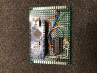
I got it built and it works great! Now that I have a working keyboard, I'm working on using Glitch's XTIDE with a CF adapter. After that, I'll be able to test it out better. The monitor I have working is a HP S2031, it's not as old I thought, 2010 model. It works great with text, I have only tested one color game on it so far. The only quirk is that it seems to sync best if you turn the monitor on after the computer. If you do get a PCB laid out, I would be interested.

IMG_0667.jpg

Thanks again,

Will
 
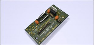
Update: I have laid down a PCB for the keyboard emulator. In the process I have also update the schematics, namely:

- removed the DIP switches and replaced them with two jumpers
- added a PS/2-style (mini-DIN) keyboard connector in parallel with the AT-style (DIN) connector
- added a full set of inspection/test points for debugging
- added a break in the 5V line from the M24

The 5V line break can be jumpered closed for powering the emulator from the M24, or left open if power is to be supplied via the USB port, or a diode soldered in there once I figure out if there's a voltage problem with that line or not :)

The software does not use the two configuration jumpers yet but I thought it would be handy to have at least two, say one for enabling/disabling debug mode and one to enable/disable the TTY-via-USB feature (not sure about this last one - if you don't want to use the TTY feature, just don't send anything down the USB data line :) ).

The two keyboard connectors are not meant to be used at the same time - their footprints on the PCB overlap, so you can solder one or the other, but not both.

The inspection points (J2) are meant to be accessed from the bottom of the PCB - pls ignore the KiCAD rendering of the pin connector row in the middle of the Arduino socket. The signal names are stencilled on the bottom but I don't know if the PCB manufacturer I use supports bottom silkscreens for "prototype" (read: cheap) production runs.

The 12V test point (12V is not used anywhere on this board) is strategically positioned so that in an emergency a 7805 can be soldered in place and the emulator powered from the 12V line instead of the 5V line, HOWEVER: the original 5V trace would need to be cut (or the relevant DB9 pin removed), a ground line soldered in place, and it would still be missing at least one capacitor on the 12V side - as I said, it would be a dirty hack, and I hope it won't be needed.

Attached are the KiCAD files, updated pdf schematic, and a partial render. Any comments/suggestions welcome.
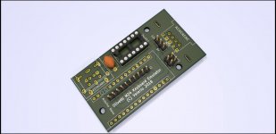
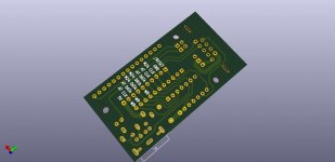
keybem_front.jpg
keybem_back.jpg
 

Attachments

  • olivetti_kb.pdf
    34.3 KB · Views: 17
  • olivetti_kb_kicad.zip
    30.2 KB · Views: 14
I got it built and it works great! Now that I have a working keyboard, I'm working on using Glitch's XTIDE with a CF adapter. After that, I'll be able to test it out better. The monitor I have working is a HP S2031, it's not as old I thought, 2010 model. It works great with text, I have only tested one color game on it so far. The only quirk is that it seems to sync best if you turn the monitor on after the computer. If you do get a PCB laid out, I would be interested.

View attachment 49286

Thanks again,

Will

Nice! Can I ask what keyboard you tested it with? Or did you use the TTY-via-USB feature?

Also, did you power it via the USB cable or from the AT&T 6300 keyboard port?

Thanks!
 
Interesting progress. Three questions:

- why not using, like original M24 keyboard, using the +12V supply with a voltage regulator?
- what is the usage of the mini-DIN keybard connector?
- M24 keyboard mouse emulation, please...?
 
- why not using, like original M24 keyboard, using the +12V supply with a voltage regulator?

The reason is that it did not seem necessary to me - 12V are not directly needed anywhere, and 5V are already provided on the keyboard connector, so why not use that? It saves at least 2 components (the regulator itself and the upstream capacitor), and it uses less power (the regulator would be a linear one, so it dissipates the excess voltage as heat).

- what is the usage of the mini-DIN keybard connector?

It's to connect keyboards with a PS/2-style connector. The keyboard protocol for AT and PS/2 keyboards is the same, only the connector is different (DIN-5 for AT keyboards, vs mini-DIN-6 for PS/2 keyboards), so the emulator should be able to work with both. On the PCB I wanted to keep the option of choosing one connector or the other.

- M24 keyboard mouse emulation, please...?

Working on it...
 
Last edited:
The reason is that it did not seem necessary to me - 12V are not directly needed anywhere, and 5V are already provided on the keyboard connector, so why not use that? It saves at least 2 components (the regulator itself and the upstream capacitor), and it uses less power (the regulator would be a linear one, so it dissipates the excess voltage as heat).
Maybe the 5V is too weak for the emulator, modern keyboard & mouse... I think you should make it configureable, so the user can choose if he wants to use 5V, or install an 7805 and use this one...
It's to connect keyboards with a PS/2-style connector. The keyboard protocol for AT and PS/2 keyboards is the same, only the connector is different (DIN-5 for AT keyboards, vs mini-DIN-6 for PS/2 keyboards), so the emulator should be able to work with both. On the PCB I wanted to keep the option of choosing one connector or the other.
Ok, I understand, good decision.
Working on it...
Yeah!


As it has USB connector, will it also be possible to 'remote control' the M24 from another PC over USB (mouse and keyboard)? That would be cool!
 
Maybe the 5V is too weak for the emulator, modern keyboard & mouse... I think you should make it configureable, so the user can choose if he wants to use 5V, or install an 7805 and use this one...

There is no mouse yet :) and with emulator and keyboard it works fine off the 5V line, even with the voltage drop. However you have a point - let me get to the bottom of the cause of this voltage drop.

As it has USB connector, will it also be possible to 'remote control' the M24 from another PC over USB (mouse and keyboard)? That would be cool!

This is already possible today with the current version of the emulator - minus the mouse. Just use PuTTY or any other terminal app of your choice that supports serial over USB, and you can control the M24 as if you were typing on its own keyboard. Not all keys are available but it's pretty usable.

I'm not sure how I would support a mouse-via-USB though - even if the emulator did emulate the M24 mouse (which should not be hard), I'm not familiar with how (or even if!) terminal apps send mouse movement (and click) information down a serial line...
 
Nice! Can I ask what keyboard you tested it with? Or did you use the TTY-via-USB feature?

Also, did you power it via the USB cable or from the AT&T 6300 keyboard port?

Thanks!

I used a Dell model RT7D5JTW PS/2 keyboard which is rated at 75mA.

I am currently using the 5V pin from the keyboard port, which in my case is providing 4.85V. It works fine to power the Arduino and a PS/2 keyboard. I am planning on adding a voltage regulator and using the 12V pin before I attempt to use my IBM Model F AT keyboard. My Hi-Tek XT/AT keyboard draws 300ma, so I can only assume that the older capacitive keyboards probably draw more.

Will
 
I run a Compaq keyboard, a BluePill ( 32 bit ARM ) and 10 led's on the USB port. It is a PS/2 to parallel but could generate M24 codes as well, by just a change to the lookup table. It could even be used take USB to the M24. The BluePill is cheaper than the Arduino's.
Such things can be done on an Arduino as well.
Dwight
 
Edited PCB attached. Looking at the 7805 datasheet it seems that in a TO-220 package it is safe to dissipate (12V - 5V) * 500mA = 3.5W while keeping the junction temperature well within the recommended operating conditions, so I did not include space for a heatsink - let me know if you think otherwise.

Also note that the space for the input / output capacitors is approx 9x9mm / 6x9mm - should be enough for ceramics or low-voltage electrolytics.

keybem_front.jpg
View attachment olivetti_kb.pdf
View attachment olivetti_kb.zip
 
I suspect the temperature will stay within operating range but I doubt it will do much to improve its life time. I'd say add a heat sink. There are a lot of variables in what it can take. Things like do the leads connect to a power plane. Will it be mounted vertical or horizontal.
Dwight
 
Back
Top