• Please review our updated Terms and Rules here

Olivetti M24 / AT&T 6300 Keyboard Emulator

Most places I looked at say case to ambient is on the order of 50 to 60 degrees C per watt.
3.5 times 50 is 175. add that to 25 = 200 degrees C. Most to-220 packages are rated at 150 C.
At 150 C, I can tell you that touching the package will flatten the finger prints so you can get away with other crimes.
Most show the die at 3.5 degrees per C so the die would be another 12.25 C hotter then that.
What numbers did you see for package to ambient?
Dwight

Ok, I admit I only checked one datasheet, this one, which gives the thermal resistance as 19 degree C/W for TO-220 packages, which would give T_J = 3.5 * 19 + 25 = 91.5 C, still too hot to touch but below the recommended max junction temperature of 125C.

TI's datasheet gives 23.9 C/W, which would bring this to 107, even hotter but borderline ok.

However now I see ST's datasheet says 50 C/W ? This would definitely mean it's way too hot, as you say.

And Fairchild's even higher at 65 C/W! I am perplexed...

Anyway I think I can rotate the 7805 so its back faces the outside of the PCB, so a heatsink can be attached...
 
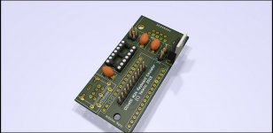
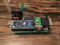
And here it is - with the regulator rotated and on the outside border of the PCB, so a heatsink can be attached.

keybem_front.jpg
 

Attachments

  • olivetti_kb_pcb.zip
    17.3 KB · Views: 21
Ok, I admit I only checked one datasheet, this one, which gives the thermal resistance as 19 degree C/W for TO-220 packages, which would give T_J = 3.5 * 19 + 25 = 91.5 C, still too hot to touch but below the recommended max junction temperature of 125C.

TI's datasheet gives 23.9 C/W, which would bring this to 107, even hotter but borderline ok.

However now I see ST's datasheet says 50 C/W ? This would definitely mean it's way too hot, as you say.

And Fairchild's even higher at 65 C/W! I am perplexed...

Anyway I think I can rotate the 7805 so its back faces the outside of the PCB, so a heatsink can be attached...

I suspect it is an error in the table. If you look at the text above the table, they say it is 54 C/W. At number that is a little closer.
Dwight
 
The PCBs have arrived!

The PCBs have arrived!

... and here they are!

The PCBs have arrived, and I have quickly assembled one to test the layout, and it works!

I have tested it with my Chicony AT keyboard (~150 mA) with both the 5V supply and with the 12V supply regulated down to 5V, and it works in both cases. In the latter case the L7805CV I have installed (with no heatsink) heats up a bit but it's still only mildly warm to the touch (I'd say less than 50C). Anyway, a heatsink can be installed if need be.

A couple of minor notes -
- I had envisaged having the option to connect this directly to the keyboard port of the M24, without a cable. So I designed the PCB with the AT or PS/2 keyboard connector facing outwards (ie, if you are facing the front of the M24, right). However I had forgotten that the M24 motherboard is upside down, and hence so is the DB9 keyboard connector! As a consequence the PCB is also upside down if connected directly and the AT or PS/2 keyboard connector then faces inwards (ie left), ie towards the power supply fan housing. I think there is enough clearance to connect a PS/2 keyboard, but probably not an AT one - sorry. I think it's just more practical to connect the emulator to the M24 with a straight male-to-female DB9 cable like this $5 one and not worry about clearances at the back.
- The PCB holes for the mounting (not signal) pins of the AT (not PS/2) keyboard connector are misaligned - sorry about that. Not a big deal as the AT connector can still be soldered securely by bending the mounting pins inwards.

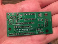
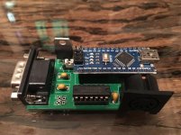
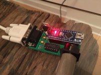
Here are some photos:

keybem_bareboard.jpg

keybem_front.jpg

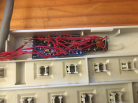
keybem_back.jpg

keybem_on.jpg

As you can see both the 74LS07 and the Arduino are socketed, and JP2/JP3 are not soldered in as they are not used yet by the firmware.

So... if you want one, pls PM me. As I said, no charge, while stocks last.
 
Last edited:
5V line

5V line

Ok, I think I got to the bottom of the behaviour of the 5V line on the keyboard connector.

Short version: the problem is with the serial cable I am using to connect the emulator to the AT&T 6300

Long version:

So as you recall, the M24 keyboard port has both a 12V pin and a 5V pin. The latter is not used by the original M24 keyboard. When using it to power the keyboard emulator directly (as well as the AT or PS/2 keyboard attached to it) I (as well as JWDW) experienced a drop in voltage on this voltage rail when measured at the emulator.

A few measurements reveal that the problem is actually with the DB9 extension cable I used. Even with full load on the emulator (ie all 3 lock leds on) measuring the voltage directly at the M24 keyboard connector on the motherboard still yields 5V (5.02V on my machine, to be precise). This voltage does not appreciably move with load on the keyboard port. It also appears that the 5V keyboard port pin is connected directly to the 5V plane of the motherboard (which appears to have at least one internal layer - the 5V power plane).

I also checked the behaviour of the 12V line and found it to be exactly the same: the voltage as measured on the emulator is up to 200mV lower than when measured on the keyboard connector on the motherboard.

All of this is consistent with the connection between keyboard port and emulator having a resistance which is sufficiently greater than zero to be causing a ohmic voltage drop.

To confirm this, I also measured directly the resistance on the 5V line and found it to be around 2 Ohm between the keyboard port (motherboard side) and the emulator (on the PCB, ie after the DB9 connector) (yes I know measurements of low resistance are hard to obtain accurately). Conversely, the resistance between the keyboard port and the 5V "master screw post" on the motherboard was essentially zero. Consistently, the resistance between the keyboard port and the emulator on the GND line was half - around 1 Ohm (which makes sense as there are two ground pins on the keyboard port, and two ground wires). In my mind this left two possible culprits: the DB9 connector(s) and/or the cable itself.

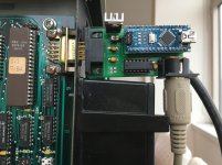
One obvious counter-experiment is to connect the emulator directly to the keyboard port. Unfortunately this is a bit tricky due to a mistake in my PCB design - the AT keyboard connector ends up clashing with the housing of the power supply fan, as shown in the photo below:

kbem_clash.jpg

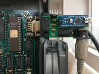
However, just for the sake of running this experiment, I removed the housing and was then able to connect the emulator directly:

kbem_nohousing.jpg

Note that I also had to remove the hex screw posts from the male DB9 connector of the emulator (which also makes the metal d-sub shell fall off...).

With this configuration I see no voltage drop.

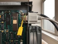
In light of all this, it seems the culprit is the DB9 serial cable. I guess possible causes are that the wires inside the cable are probably very thin (and not meant to be carrying significant amounts of current) and/or that the cable connector makes poor contact with the motherboard keyboard port. See how the fact that the keyboard port is quite recessed means the cable shell can never be fully inserted:

kbport_cable.jpg

(btw the yellow probe is where I measured the 5V on the motherboard keyboard connector)

So I guess the take-away is that in the next iteration of the PCB layout I will
- make it possible to connect it directly (possibly mounting the DB9 connector to the bottom of the PCB)
- leave more space for a wrap-around heatsink (it turns out Dwight was right - you really do need one for any extended use of the voltage regulator)
- fix a few minor layout glitches (ie mounting pins for the AT connector, and a different Arduino digital pin for JP2)
 
How to connect a mouse for the emulation of the keyboard-mouse?

I haven't got that far yet - this is just the PCB for the keyboard-only emulator. When I finish the mouse version it will have two connectors - one for the (AT or PS/2) keyboard and one for the (PS/2) mouse.

Incidentally I realised I cannot use the Arduino Nano for the combined keyboard+mouse emulator, since the ATmega 328-type chips only have two external hardware interrupts, and I will need three (one for each clock line: M24, AT keyboard, PS/2 mouse). So I guess I will switch to a 32u4-based board.
 
For reference, attached is the latest version of the firmware. No major changes, but now JP3 actually has a function:

- CLOSED (ie tied to GND): debug mode on, ie debug info is sent via USB for each keystroke or other event [default setting]
- OPEN: debug mode off

JP2 is still not used.

JP1 is as on the silkscreen on the back.
 

Attachments

  • m24kbem100.zip
    8.6 KB · Views: 23
I haven't got that far yet - this is just the PCB for the keyboard-only emulator. When I finish the mouse version it will have two connectors - one for the (AT or PS/2) keyboard and one for the (PS/2) mouse.

Incidentally I realised I cannot use the Arduino Nano for the combined keyboard+mouse emulator, since the ATmega 328-type chips only have two external hardware interrupts, and I will need three (one for each clock line: M24, AT keyboard, PS/2 mouse). So I guess I will switch to a 32u4-based board.

If you can't buy the 32u4 for cheaper than $3 you might consider the blue pill boards. These use the STM32F103 that has plenty of interrupt pins. The F103 has many 5v tolerant pins and shouldn't need the buffer. I'm not sure what you need interrupts for though. Both the keyboard and the mouse can be throttled and polled for data. You can handle all with just polling.
Dwight
 
Great work so far. Keep it up! I am going to order some of these boards and give it a go. It would be nice to have a USB option to connect any keyboard to it, but then I am sure the signaling would all be different. I ran across this project and was heading down that direction, but this is a simpler design.
 
So I guess the take-away is that in the next iteration of the PCB layout I will
- make it possible to connect it directly (possibly mounting the DB9 connector to the bottom of the PCB)
- leave more space for a wrap-around heatsink (it turns out Dwight was right - you really do need one for any extended use of the voltage regulator)
- fix a few minor layout glitches (ie mounting pins for the AT connector, and a different Arduino digital pin for JP2)

Valerio,

Did you ever get anywhere with your updates? I was going to hack around on your board to make the suggestions above, but no need if you have already done it. :)
 
Really interesting project! Read it through!

I have an Keyboard 2 as well, I have plans to build a simple adapter for the serial port, add power supply for the 12V (I could remove the component so it would work with 5V, but I don't want to change the inside and write a program in Python to communicate through the RS232, we will see if it would work.
 
Great project, great research, great write-up. My only comment is that the type 2 keyboard was either not offered by AT&T (I've never seen one AT&T-branded), or was so uncommon that it isn't worth attempting to emulate as nothing supported it. A scancode conversion of an AT keyboard to the Type 1 keyboard would be 99.9% sufficient.

For the M24, that may be a different story, but I've never seen or held a Type 2 keyboard, sorry.

And now I get to eat my words, as I just found an auction with KBD 302 keyboards. I ordered one and will test it out. I have some AT&T people in the area that I will ask to try to get more history about this variant; the USA 6300 type 2 version appears customized for a specific call-center application.
 
There is only one problem left (I think), and this is where I'd welcome any help or suggestion.

I have not been able to understand what the expected behaviour of the original M24 keyboard is upon reset (remember, I do not currently have access to my own original M24 keyboard). As a consequence, in the BIOS POST routine the emulator is not recognized as a "deluxe" (Type 2) keyboard and the system defaults to the 82-key, "Type 1" keyboard. This means that some scancodes are misinterpreted by the BIOS. This is not a huge deal, as they two types are pretty similar. Also, the keyboard type flag can be corrected in software later on rather easily (bit 0 of the byte at 0040:0018 controls the keyboard type).

Similarly, the CUSTOMER.EXE program fails to recognize that there's a keyboard attached. Using SYSTEM.EXE you can force to run keyboard tests anyway but the output is a bit weird, which bring me to my first actual question (btw thanks for reading so far!):

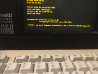
- what should the "keyboard test" section of CUSTOMER.EXE / SYSTEM.EXE look like when connected to a real Type 2 keyboard? Can someone post a screenshot? Mine looks like this:

View attachment 1024964

I dug into the BIOS listing and this is the relevant code (see page 416 of the System Programmer's Guide) - this is executed just after the "beep" (ie after the RAM test and the "RT Clock Pass" message):

Code:
    mov dx,p_kctrl         ; dx = p_kctrl
    mov al,40h         ; remove keyboard reset
    out dx, al

    mov ah,1             ; enable self test
    call kb_cmd_send
    mov word ptr ds:[reset_flag],cx        ;; cx is zero here
    xor cx, cx                    
    loop $                        ; delay

; Flush any keyboard scan code and store AAh if we get it.
kb_flush:
    in al,kb_status        ; get 8041 status
    test al,1             ; test output buffer bit
    ja kb_flush_back     ; jump if no character pending
    in al,p_kscan         ; get scan code from data port
    cmp al,0AAh         ; verify keyboard present
    jne kb_flush
    mov word ptr ds : [reset_flag],ax ; keyboard present
kb_flush_back:
    loop kb_flush         ; loop If zero
    xor cx, cx         ; delay
    loop $

;; other memory variables init stuff

; Assume first not Deluxe Keyboard
    and byte ptr ds:[kb_flag_1],(not dlx_kb)

; Send command to request ID code from keyboard.
    mov ah,05H         ; Read keyboard type
    call kb_cmd_send     ; -- send command.
    xor cx, cx         ; set up timeout count
kb_type_wait:
    in al,kb_status     ; get port status
    test al,l             ; data byte available?
    jnz kb_type_read     ; If so, go read it . .
    loop kb_type_wait     ; else wait awhile longer.
    jmp kb_not_dlx         ; timeout, default to non-dlx
kb_type_read:
    in al,p_kscan         ; read ID byte..
    test al,01H         ; deluxe kbd. bit set?
    jz kb_not_dlx

; 01H bit set, so initialize to Deluxe Keyboard.
    or byte ptr ds:[kb_flag_1],dlx_kb
kb_not_dlx:

(single semicolon comments are the original ones. Double semicolon ones are mine)
For reference,

Code:
p_kscan    equ 060h
p_kctrl    equ 061h
kb_status    equ 064h

So there are three distinct parts:
a) "remove keyboard reset", ie release the clock line which, until that point, had been kept low (logic 0). Presumably this is what kept the keyboard LEDs blinking on the original keyboard (the Theory of Operation manual says that clock low for longer than 50ms triggers a reset).
b) "enable self test". This makes the keyboard controller send 0x10 (not 0x01!) to the keyboard. It then waits for 0xAA, which the emulator dutifully sends as soon as it spots the 0x10 from the M24. So far so good (I think).
c) "read keyboard type". This is where things go wrong. The code sends 0x05 to the data port of the keyboard controller (p_kscan), but nothing happens: nothing is sent to the keyboard itself. So the emulator does not know when to send its reply. The next IN operation always returns 0, and the keyboard is assumed to be non-deluxe.

This is where I'm stuck. I have tried several things (eg send another byte after 0xAA), but it made no difference. Incidentally CUSTOMER.EXE / SYSTEM.EXE seem to do the same thing - ie reset via the clock line & send 0x10, several times actually - but I can't get them to recognize that a keyboard is present (let alone which type).

I have now bitten the bullet and bought an AT&T keyboard off eBay so I can try and sniff the exchange, however it's not a "deluxe" type so it may not help me (and it hasn't arrived yet).

Any ideas?

Attached for your reference is the schematic I'm using (dip switches and M24 "sniffer" keyboard connector not implemented yet) and the source code. As always, if you want to experiment, use at your own risk...
Hi Valerio,
you mention "see page 416 of the System Programmer's Guide", but I'm not able to find the Guide you're referring to... can you please share the document or a link?
Thank you,
Duccio
 
Back
Top