• Please review our updated Terms and Rules here

omg omg omg, I just got an IBM 5162!

Assuming my 5150 powers on, posts and boots with my TEST PSU, we can "assume" that it's good? Or at least capable of producing a POWER GOOD signal? Or are you implying that I need to probe the 82284 chip? (and if so, how? Find POWER GOOD pin and use continuity again ground? Seriously, I know so little...)
A visual representation of the POWER GOOD signal generation is at [here].

A 'perfectly good' power supply will not take its POWER GOOD signal high if the power supply is overloaded. A short-circuit capacitor on the motherboard is an example cause (one of many causes).

Some 'perfectly good' power supplies will not take their POWER GOOD signal high if the power supply is underloaded. For example, the 5162 motherboard alone is sometimes not enough of a load for the 5162's (IBM supplied) power supply.


To measure the POWER GOOD signal:
1. Power on your configuration (your known good "TEST PSU", plus 5162 motherboard, plus something that uses +12V for 'good measure')
2. Place multimeter in 'DC voltage' mode.
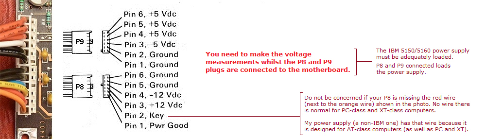
3. Negative probe of multimeter to a ground pin of P8 or P9, per image below. Note the red text in the image.
4. Positive probe of multimeter to the POWER GOOD pin ('Pwr good' in image below) of P8. Note the red text in the image.
5. If the multimeter shows 2.4V or more, that means the POWER GOOD signal is 'high' - what is expected.

p8_p9_pinout.jpg
 
Yes, to be specific: Set your DMM to low-range ohms (some have a audible continuity check as well). Disconnect the power supply from the motherboard, then connect one DMM lead (the black - one is good) and then probe the other power input pins on the motherboard. You should get close to 0 ohms on the other ground pins, but nowhere near that on the others. An abnormally low resistance indicates a shorted component.

PSU unplugged from AC, DMM set to 2k ohm

First black wire used as ground
2nd black wire - 0.00
white wire - .099
red wire - .094
red wire - .094
red wire - .094

black wire - 0.00
black wire - 0.00
blue wire - .394
yellow wire - .146
red wire - .092
orange wire - 1.089

Does this tell us anything? It did fire up my 5150 with no obvious issues.

As for testing the tantalum caps, what setting on the DMM should I use and what is the desired value range?

TIA

Kind Regards,

-JDT
 
I haven't read the majority of this post either, but it seems like Chuck was telling you to ohm the motherboard pins. I thought it was established your p/s was good.
 
I haven't read the majority of this post either, but it seems like Chuck was telling you to ohm the motherboard pins. I thought it was established your p/s was good.

Then apparently I need to learn how to read =)
 
If the multimeter shows 2.4V or more, that means the POWER GOOD signal is 'high' - what is expected.

p8_p9_pinout.jpg

Pwr Good was at 4.6v so... signal was high
a few anomalies, -5v was actually -4.6v and the -12v was -11.4, within tolerances?
 
I don't believe that -5 is used for anything on the 5162. -12V mostly gets used for RS232 levels, so it won't prevent your system from running. +5 and +12 are the important ones.
 
Pwr Good was at 4.6v so... signal was high
Good. (Pun intended.)

As for testing the tantalum caps, what setting on the DMM should I use and what is the desired value range?
No need anymore. If there was a short-circuit capacitor on the motherboard (what some people are asking you to look for), it would have overloaded the power supply, with the result that the power supply would not have taken the POWER GOOD signal high.

a few anomalies, -5v was actually -4.6v and the -12v was -11.4, within tolerances?
As Chuck(G) wrote, not of concern for a 5162 motherboard. What your 5162 motherboard needs to start, is +5V, and the POWER GOOD signal transisioning from low to high, and you are seeing both of those.

So now your focus is the motherboard. Your newly acquired POST card did not display any codes, which is bad news, however, maybe the POST card (made in China I presume) is faulty in some regards. Do you have another ISA bus computer (286 or above) to test it in ?

Per Chuck(G)'s suggestion, if you have a suitable video card (e.g. VGA is unsuitable) for them, use of the Supersoft/Landmark diagnostic ROM's is worth trying.
 
Something to add, the original battery leaked all over the 5-pin DIN keyboard connector, pins 4 & 5 have continuity, as do the through-hole mounts on the bottom... thinking its a problem.
Using this diagram.
FPQ8XUMHPG4NMTS.LARGE.jpg
https://cdn.instructables.com/FPQ/8XUM/HPG4NMTS/FPQ8XUMHPG4NMTS.LARGE.jpg

What are your thoughts? I'm handy-enough with a soldering iron, I could probably remove the DIN connector, maybe clean it up and re-attach (or replace).
 
Last edited:
You really want to check to see if there are other traces corroded around the connector. Through-hole continuity isn't sufficient--you want to see if there's continuity between the connector and the ultimate destination of the signal lines (i.e. the 8042 keyboard controller)
 
You really want to check to see if there are other traces corroded around the connector. Through-hole continuity isn't sufficient--you want to see if there's continuity between the connector and the ultimate destination of the signal lines (i.e. the 8042 keyboard controller)


I happened to have my 5160 mobo here with me as well, and the same continuity does not exist pin-to-pin or solder joint-to-solder joint.
So I'm looking for a 8042 keyboard controller, google image-searching shows a longer 40-pin IC, but (and I forgot my glasses today) I do not see any chips marked 8042. Tried following the traces from the DIN... maybe they used a different KB controller chip? I'll google the larger chips to see if I can find it. The IC marked Intel 8742 looks like what I'm looking for... now to figure out how one goes about testing it.
 
Last edited:
Not even for the composite output (RCA-style) jack on the CGA card?

... interesting, I'll have to look at them again when I get home. But either way I'll still have to acquire eproms and a burner (recommendations?)
 
So I cleanly removed the DIN connector... a little bit of corrosion under it, cleaned it up. However, the pin-holes for pins 4 & 5 still show continuity... and if I probe either of those pin-holes (or the DIN main ground) I can get continuity to various pins on the 8742 chip to pins 20 (vss), 26 (vdd), & 40 (vcc) - I've no idea what this "means"
 
The 8742 basically the same as the 8042; one is field-programmable, the other is factory-programmed.

If you want to see how all of this is connected, consult the IBM techref schematic for the 5170, if there's no 5162-specific one available. The connections are the same.
 
The 8742 basically the same as the 8042; one is field-programmable, the other is factory-programmed.

If you want to see how all of this is connected, consult the IBM techref schematic for the 5170, if there's no 5162-specific one available. The connections are the same.

Will look for that, do you know if the tech ref's provide troubleshooting (probing) instructions / values?

EDIT:
Somewhere above, I mentioned that all 3 LEDs are illuminated and are stuck on when a AT keyboard was plugged in, I think I've got a short... but how the heck to find it...
I found a 5162 Tech Ref on the minuszerodegrees site, awesome site... maybe something lucky will pop out at me.
 
Last edited:
I'll still have to acquire eproms and a burner (recommendations?)
You do have the option of getting someone to send you programmed EPROM's.
Some people who can do that are shown at [here].
The images and EPROM details required for that are at [here]. (The Supersoft/Landmark ROM's for the 5170 also apply to the 5162.)
 
So I cleanly removed the DIN connector... a little bit of corrosion under it, cleaned it up. However, the pin-holes for pins 4 & 5 still show continuity... and if I probe either of those pin-holes (or the DIN main ground) I can get continuity to various pins on the 8742 chip to pins 20 (vss), 26 (vdd), & 40 (vcc) - I've no idea what this "means"
From the 5162's technical reference, the motherboard's keyboard interface circuitry is shown at [here].

As you can see, there is circuitry between the 8042 (or 8742 for the EPROM version) and the DIN connector.

However, both pin 4 of the DIN connector and the 8042's Vss pin are tied to ground. So expected, is a measurement of zero ohms (or close to) between the two.

Also, both pin 5 of the DIN connector and the 8042's Vdd pin are tied to +5V. So expected, is a measurement of zero ohms (or close to) between the two.

When you measure between pins 4 and 5 of the DIN connector, you measuring the resistance between the +5V line and ground line. In effect, that is measuring the combined parallel resistance of all components on the +5V line. It will be low, but not zero ohms (or close to), otherwise the +5V line of the power supply would have been overloaded. As an example, on one of my 5170 motherboards, I measure about 200 ohms between the +5V line and ground.

By the way, the 'continuity' mode of a multimeter can be misleading. If you are using it, use the resistance mode instead. And if your multimeter is not auto-ranging, select a range appropriate for the measurement expected. (There are web sites that cover this kind of stuff.)
 
Back
Top