• Please review our updated Terms and Rules here

Osborne I - no disk drive response

NutmegCT

Experienced Member
Joined
Jul 24, 2009
Messages
153
Location
Connecticut
Good morning all. Haven't been here since 2009!

I'm looking for assistance on diagnosing and repairing my Osborne I. It's been running fine for many years; I stored it for a few months, and today tried it again. No luck.

Beige case, s/n A 14649.

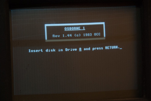
Powered on, screen prompts to insert system disk into Drive A and hit return.

I insert the disk, close the drive door, and hit return. There's no disk drive action. Same for using the B drive with Shift/+.

When I first power up the Osborne, the A drive red light flashes once. No further response from A or B. I've opened the case and find no loose connections or obvious problems.

Thanks!
Tom Morehouse
Eastford CT
 
We have another thread running for an Osborne 1 repair at the moment. See my post history for the other thread. I will think about your problem at the same time...

Dave
 
I am just chasing down the boot code.

Question - does it just 'hang' (i.e. you get no drive select, no motor operation and no error message)?

Question - how do you know the keyboard is working (i.e. the boot ROM is actually seeing any characters you are pressing)?

Dave
 
I am just chasing down the boot code.

Question - does it just 'hang' (i.e. you get no drive select, no motor operation and no error message)?

Question - how do you know the keyboard is working (i.e. the boot ROM is actually seeing any characters you are pressing)?

Dave

Thanks for digging!

Neither drive moves when powering up, or after I hit <return> after inserting system disk and closing A drive door. Same for B drive.

Only life I see when powering up is (1) a brief flash of the red light on drive A, and (2) the screen shows the normal Osborne - please insert system disk and press <return>

13944884113_9dc163c16b.jpg


Good point about the keyboard; I don't know how to tell if it's working. It's an Oak FTM, connecting to the m/board with a long multi-color "rainbow" cable. Similar to this:

13944910653_1e1bc30694.jpg


One thing: if I power up when it's been sitting cold for an hour or so, sometimes the CRT flickers with the opening logo. If I hold down the Return key for a few seconds, the flicker stops and the screen is normal.

It's the keyboard I've had for many years. Seems very well built and "rugged" - as well as clean.
Thanks.
Tom M.
 
Last edited:
The keyboard itself just insists of a matrix of keys. You can see the connector in the technical manual on page 41 onwards of http://www.bitsavers.org/pdf/osborne/osborne1/2F00153-01_Osborne1TechnicalManual_1982.pdf (assuming this technical manual looks like what you have got of course).

You should be able to remove the keyboard connector from the main board(s) and checkout the key switch matrix with a multimeter set to measure on a low resistance continuity range.

Does this make sense to you? Not sure how much you know about electronics, repair techniques, reading schematics or whether you even have any test equipment.

So the fact that you get a brief flash on the drive select light initially means that the light is working! Presumably this light never comes on again no matter what you do with the keyboard? In order to get the drive motor to spin up - I think you need the drive select light ON in the first place (although, bizarrely, I can't find the drive select LED on the schematic for the disk drive).

Dave

Thanks for the tech reference. I can understand the matrix, but sadly I don't have a clue how to test it. I have a good multimeter, and have been testing continuity since I was a teenager. But to put it bluntly, I don't know what pins on the keyboard connector I'd be testing. (In other words, which two pins to put my test leads on.)

I vaguely recall that when the drives were working last year, the red light comes on when the drive is spinning. So other than at power-up when the A light goes on and then immediately off, it never goes back on (and the A drive doesn't spin when I hit Return). At power-up, the B light never does the on and off routine, but I don't know if it should.

I do know that if I put the system disk in the B drive, and do the Shift+ key combo to boot from the B drive, nothing happens at all.

By the way, my opening screen shows Rev. 1.4 (c) 1982. Not the Rev 1.44 (c) 1983 in the photo.

Thanks.
Tom M.
 
That's OK - now I know where you are (technically).

It is getting a little late in the UK - so I will post some more basic level testing of the keyboard with a multimeter later on tomorrow morning (my time) for you.

Dave
 
Thanks Dave.
Tom M.

That's OK - now I know where you are (technically).

It is getting a little late in the UK - so I will post some more basic level testing of the keyboard with a multimeter later on tomorrow morning (my time) for you.

Dave
 
Update at 0800 EST. I removed the multi-line keyboard cable, and checked continuity for each line. Good for each line.

I'm thinking that cable is a replacement; each line is a different color, the cable is over three feet long, and it was taped to the keyboard base with duct tape, which also covered a tiny spring just sitting free. Also, the terminal at each end has no raised "key block" to align into the center gap of each pin connector; the cable *could* be inserted upside down with no problem. I marked the original position, but have no guarantee it's correct - altho' it had been working for years.

A quick test might be, if I could just "short" the two proper pins on the m/board keyboard connector, to emulate a <return> key being pressed. If the quick test results in the drive spinning, that would indicate the keyboard is the problem. If the quick test fails, then the problem likely isn't the keyboard.

But I don't know which two pins on the m/board keyboard connector to use for the quick test! In other words, how do the pins in the cable connector correlate to the matrix diagram in the tech manual? Photo of connector attached.

IMG_0449.jpg

Thanks.
Tom M.
 
Last edited:
Sorry, my trip today took way longer than I imagined it would. I am buying a new car. Unfortunately, what the dealership ordered and what I wanted was not quite the same thing! Sorted now - have to wait for a new new car to be built in the factory!

First things first...

Note EXACTLY how the keyboard is attached to the cable and how the cable is attached to the main board. Hopefully, it should not be possible to re-assemble things incorrectly - but (just in case you can) take copious notes and photographs.

There is usually some sort of indicator to indicate pin 1 - be it a square pad on the PCB, the number '1' on the PCB silk screen, or a triangular mark (or otherwise) on the connector itself. However (as in some of the systems we have at work) pin 1 (as indicated) may not actually be pin 1!

The safest way I know of would be to disconnect ONLY the cable from the keyboard (noting the way it was inserted) and using your multimeter (set to indicate continuity/resistance) on the pins of the keyboard. There are no active devices at all on the keyboard - so it should be impossible to do any damage to it with a simple multimeter...

What you are trying to do is to detect (by the continuity) a low resistance when the RETURN key is pressed between two of the pins and a high resistance when the RETURN key is not pressed. You may be able to trace the PCB wiring out from the RETURN key to the connector. Alternatively, you can measure the resistance from one side of the RETURN key to the keyboard connector and then from the other side of the RETURN key to the keyboard connector. Once you have done this (and found out which two pins of the keyboard connector are physically connected to the two sides of the RETURN key) you can perform the test itself. You have now identified pins 3 and 15 on the keyboard connector (!) and (assuming you get the appropriate resistance readings with the key depressed and released) - we have identified whether the key itself is actually working or not.

By now knowing which two pins of the keyboard connector have the RETURN key connected - you can (if you wish) jumper these two known pins with a piece of wire to see if you get any response directly from the Osborne 1 when you power it up to the boot prompt. It is also usually easier to poke wire in the end of the ribbon cable socket (female connector) rather than on the male pins of the connector on the main board (my preference).

The other thing you may need to look for is shorted keys in the key matrix. A shorted key may confuse the firmware also.

Hope this is making sense?

Dave
 
Last edited:
Success! Return key uses pins 3 and 9 (top row on m/board connector). I checked by testing continuity on every possible combination at the end of the cable. Cable was plugged into keyboard. So to me, that means the keyboard (at least the return key!) and cable (at least those two wires) are good.

I shunted those two pins, and A drive spun, system loaded.

So ... what's the next step? If the Return key does close the circuit on pins 3 and 9, and 3 and 9 on the m/board connector do operate A drive when shunted ... what's causing the problem?

Thanks!

And Verault - good to meet you! I wrote my doctoral dissertation on this machine, so it's good to have a possibility that it'll run again. What got you into Osborne? (I also have a couple of Tandy 102s.)

Tom M.
 
Update: after shunting 3 and 9 and getting the system going, I decided to re-attach the keyboard and cable.

The system immediately made a high pitch beep, which stopped when I disconnected the cable.

I then disconnected the cable from the keyboard, and plugged the cable into the m/board connector. No beep this time.

Then plugged the other end of the cable back into the keyboard - got the beep, and a random series of characters on the screen.

So to my inexperienced brain, the problem is the keyboard, not the cable.

TM
 
Firstly, good news that we know the Osborne 1 electronics and the drive are good :)!

With this type of connector, the pins alternate between the top and the bottom row - so all the odd-numbers are on one long side and all of the even numbers are on the other long side.

So what you are describing as pins 3 and 9 are actually pins 15 and 3 respectively. See if it makes sense to you and compare that with the drawing you posted above (remembering that one of the edge pins is missing)...

Code:
[FONT=Courier New]1 3 5 7  9 11 13 15 17 19
2 4 6 8 10 12 14 16 18 20[/FONT]

Hopefully, with a bit of brain bashing, you will see the correspondence between the connector itself and the key matrix in your picture...

It may be that you have a key that is shorted out. The only way to check for this is to understand the key matrix and to painstakingly check out the keys individually.

The other possibility is a small strand of ribbon cable is shorting out somewhere - or a bad connection between the ribbon cable and one of the connectors. Again, you need to test every core of the cable out to it's partner at the other end for correct conductivity and to check from each core to every other core for an accidental short circuit. Believe me, I have been here on a number of occasions before...

Dave
 
Last edited:
Excellent. Now I understand how to interpret the matrix and connector relationship.

I have already tested each wire of the ribbon cable (disconnected from everything) for continuity. Each checks out strong - wiggling makes no changes.

Question 1: As I mentioned earlier, the top right pin in my m/board connector is missing (see photo). Is that bad? or is that how it was manufactured?

Question 2: Two pins on the keyboard itself seem to be shorted; multimeter leads show a completed circuit between those two, with no keys pressed. Offhand can't remember which two. Is this bad? or are there two "common" pins?

Thanks.
Tom M.
 
>>> Excellent. Now I understand how to interpret the matrix and connector relationship.

That's the first hurdle jumped!

>>> I have already tested each wire of the ribbon cable (disconnected from everything) for continuity. Each checks out strong - wiggling makes no changes.

It is just as important that each wire of the ribbon cable is isolated from each other as well. You need to check for this as well as correct continuity.

>>> Question 1: As I mentioned earlier, the top right pin in my m/board connector is missing (see photo). Is that bad? or is that how it was manufactured?

From the technical manual it looks like pins 18 and 19 are no connection. I see from your photograph that the missing pin is at one end of the connector. If this is pin 19 - this is OK (it appears to be not used). Sometimes manufacturers 'break off' (or more correctly remove) one of the unused pins. Generally, there is a 'blanking pin' inserted into the mating connector to prevent them from being inserted the wrong way around. If you have had the machine from new - and haven't fiddled with it before or had it away for repair - then this was most likely at manufacturing.

>>> Question 2: Two pins on the keyboard itself seem to be shorted; multimeter leads show a completed circuit between those two, with no keys pressed. Offhand can't remember which two. Is this bad? or are there two "common" pins?

There are two 'ground' pins (pins 1 and 20). These may be directly connected together on the keyboard - which may account for your 'short circuit'. If the two pins weren't pins 1 and 20 - you may have found your problem :)!

Dave
 
Back
Top