• Please review our updated Terms and Rules here

PDP-11/34 restoration

I ended up replacing the 2W carbon resistor with a 5W wire wound resistor which is rather big.
It seems to run a bit cooler (65 degrees C versus previously 70 degrees C), but I now question the wisdom of this change.
I might get a new 2W version and undo my "fix".

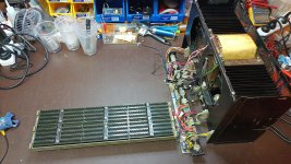
Next step will be to remove the first backplane from the chassis and mount it on some stand-offs to allow easy bench testing of the 11/34 PCBs.
 
Oh no - I am back to square one with my H754.

The H754 was running fine for a while without load, but today morning after about 2 hours of running inside the BA-11K the 20V and -5V rails disappeared. The symptoms were identical to when the +20V and -5V adjustments pots were turned too high.

I have since removed the H754 and have been testing it on the bench and can now reproduce the problem (or something similar???) by simply disconnecting a previously connected 30 Ohm load resistor between the 20V and -5V outputs while the power is on.

The SCR fires and shorts to ground, actually about 0.7V and the SCR remains triggered. If I reconnect the 30 Ohm load and momentarily short the SCR's cathode and anode the 25V returns.

It appears that the disconnection of the 30 Ohm load causes some instability in the regulations causing some voltage overshoot which in turn is causing the SCR to fire. There is a large 1000 uF cap between GND and 20V and a 2200 uF cap between 20V and -5V which should smooth any brief overshoot.

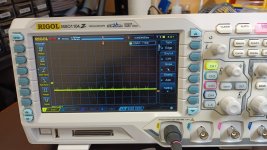
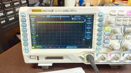
I hooked up my scope to check the +20V and -5V rails and see the following (please click on the pictures to see the full size image):
IMG_20230910_233529822.jpg

Hmmm that is -5V with lots of ripple.
IMG_20230910_233503978_HDR.jpg

+20V is not much better.

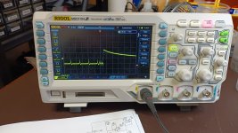
I did my "load disconnect trick" and this is what I see on base of Q12 (which triggers the SCR for -5V overvoltage):
IMG_20230910_231927478.jpg

So yes the -5V rail has not just ripples, but as a result of the "load disconnect trick" the rail badly glitches.

But hang on - we have decent size caps to take care of ripple and glitches.

I dug through my electrolytic caps and found a 470 uF 35V which was not really a replacement for the large 2200 uF cap (C9), but I was curious what would happen if I just put it in parallel with C9. The result was pleasing. No more ripple on either 20V or -5V rails and my "load disconnect trick" no longer triggered the SCR.

I then removed the old C9 completely neither ripple nor SCR triggering came back.

Unfortunately I have no way to test the old C9, but it certainly did not contribute to ripple or glitch smoothing. The much smaller 470 uF cap did a sufficient job.

So it seems all along C9 was causing all the headache. Unfortunately it is unlikely that I will find a new exact match screw in replacement, so I will probably just solder in a leaded component.

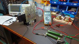
Here is a photo showing my test setup and the temporary 470 uF replacement cap and the old C9 in front of the PCB:
IMG_20230911_000007858.jpg

Tomorrow I will see if I can find a 2200 uF replacement cap locally.

Note to myself: check all the other rails (+15V, -15V, +5V) with the scope for ripple.
 
Last edited:
Nice work on the power supply. I had a similar experience with an H777 supply in a PDP-11/24 a while ago where the crowbar kept triggering due to a bad electrolytic. I find it interesting though that you have an H754 regulator since that would indicate to me that your machine has (or had) core memory and I would imagine that relatively few 11/34’s were sold like that.
 
Thanks for the compliment.

My 11/34 did not come with core but a 256K MOS memory (a M7891-DB with a red "faulty" tag).
I do have a Unibus 16K core memory (MM11-DP which is a H222 sandwiched to a G652) which is described in the 11/34 manual so it certainly was an option, just it did not come with the 11/34.
 
With nice and stable power on all rails I am about to start debugging the various boards in the system.

To make this a bit easier I will remove the "main" (first) backplane which is the the home of the two CPU boards (M7266 and M7265), Programmer's console board (M7859), RAM, etc. This "main" backplane will live on my bench for the time being.

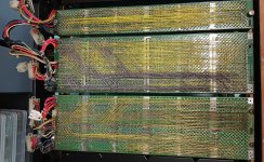
Below is a photo of all 3 backplanes and I wonder what the backplanes number 2 and 3 are meant to be for?

Coming from the nice uniform Omnibus universe these "messy" 11/34 backplanes are confusing for me.

Please click on the photo to see the full size image.

IMG_20230914_215537215.jpg
 
Below is a photo of all 3 backplanes and I wonder what the backplanes number 2 and 3 are meant to be for?
If you detach each SU (System Unit; DEC-speak for a "backplane" in this case) and lift it out enough then you can read the label on the side ... whereupon all will be revealed :-}. From here they both look like specialty controllers, not a generic DD11 with SPC slots.
 
Last edited:
If you detach each SU (System Unit; DEC-speak for a "backplane" in this case) and lift it out enough then you can read the label on the side ... whereupon all will be revealed :-}. From here they both look like specialty controllers, not a generic DD11 with SPC slots.
Actually, the middle SU clearly states RK611 on the etch, that's an RK06 disk drive controller.

If the other is 54-11560 then that _is_ a DD11-CK ... and I need to update my visual recognition algorithm. That would give you 4 SPC slots.
 
Thanks Paul. So what is a DD11-CK (the last backplane)?

Edit:
Oh our messages crossed over.

So a DD11-CK gives me 4 extra useful slots as opposed to the for me useless "speciality" RK611 for a RK06 disk drive controller I do not have?

Confusing this PDP-11. :(
 
So a DD11-CK gives me 4 extra useful slots as opposed to the for me useless "speciality" RK611 for a RK06 disk drive controller I do not have?
Yes. You can think of the DD11-CK, and it's bigger brother the DD11-DK (9 slot), as more like the Omnibus, but only a little bit. Basically slots A-B are the bus, and C-D-E-F typically house a quad-height "Small Peripheral Controller" (SPC) module, or under special circumstances (including not in either end-row) a hex-height module that doesn't actually employ slots A-B. But there are some special rules/situations that enable hex-height memory boards to be used (see "EUB" Extended Unibus)..

See the PDP-11 Bus Handbook to get started :-}. http://bitsavers.trailing-edge.com/pdf/dec/pdp11/handbooks/PDP11_BusHandbook1979.pdf
 
Ready for debugging, but first I need to do a lot more reading to understand more about what I am doing.
What set of modules have you? A basic installation with support for an RL01/RL02 disk drive would look like the attached, assuming that you use the M9202 to connect your DD11-CK. If not then you'll need a M9302 Unibus Terminator in the last slot.
 

Attachments

  • Basic 11_34.jpg
    Basic 11_34.jpg
    79.8 KB · Views: 7
.... as opposed to the for me useless "speciality" RK611 for a RK06 disk drive controller I do not have?
I've never taken a close look at the RK611 2 SU backplane. It may be that once the wire-wrap is removed that it is sufficiently "clean" that it could be re-wrapped as a DD11-DK. The problem is whether the PCB includes traces, especially if those traces are hidden on the inaccessible side facing the connector block (you could cut the visible ones). In the early days DEC single-SU units didn't use PCBs, just a few strap-chains for the power lines so it was possible to rewrap an (or use an uncommitted) SU to meet specialty requirements. When they moved to using PCBs typically there are long-run traces added in opposite directions on both sides of the PCB and wire-wrap is limited to diagonal-ish signals. That RK611 2 SU is pretty dense in wire-wrap and just might clean up to something that you could re-purpose ... if you have the time, interest, and "burning need".

In the meantime between the SPC slots on the main SU plus the DD11-CK I suspect that you have sufficient expansion capacity in-hand.
 
What set of modules have you? A basic installation with support for an RL01/RL02 disk drive would look like the attached, assuming that you use the M9202 to connect your DD11-CK. If not then you'll need a M9302 Unibus Terminator in the last slot.
Here is a list of my boards as found in the machine:

IDSlotFmtDescription
M726616CPU KD11-E (control module) Faulty (red paper tag attached)
M726526CPU KD11-E (data path module)
M82643411/34 No sack time-out
M7891-DB46256 KB MOS RAM with Parity Faulty (red paper tag attached)
5
G727364Bus Grant & Non-processor grant (PCB only)
M785674DL11-W RS232 Serial i/f & real-time clock
M781986DZ11-A 8-line double-buffered async EIA with modem control (50 to 96-Kbaud, 64-byte silo)
M785994Programmer’s console interface board
M931292Bootstrap/terminator with multiple ROMs. Damaged
M7258104Printer controller (Dataproducts interface)
M7800114Asynchronous transmitter/receiver (110-2400 baud)

None of these boards have been powered up or tested by myself up to now.
 
How to you reckon on 11 slots in a 9 slot unit?
If "Fmt" is supposed to be the number of tabs on a module ("height") then note that the G7273 is dual-height. And it goes into the C-D position. Be careful which slots and tab-positions you use for the different modules. Damage may otherwise result.

BTW, according to "MP00105_RK611_schem_Aug77.pdf" page 28-of-67 "Module Utilization" the first three slots are SPC so you are in a bit of luck :->. Read the Notes on that page for the caveats.

You may want to read: https://gunkies.org/wiki/M8264_No-SACK_Timeout_Module
 
How to you reckon on 11 slots in a 9 slot unit?
I'm guessing that #10 and #11 were two slots in the RK611 backplane, with a large gap of empty slots for the missing controller modules, but then I don't see a M9202 or equivalent listed that would be needed to bridge the Unibus to the RK611 backplane. And the M9312 wouldn't be in slot 9 since that's where the M9202 belongs. As matters seem to currently stand the M7258 and M7800 seem to have been simply "warehoused" in unconnected slots.
 
I'm guessing that #10 and #11 were two slots in the RK611 backplane, with a large gap of empty slots for the missing controller modules, but then I don't see a M9202 or equivalent listed that would be needed to bridge the Unibus to the RK611 backplane. And the M9312 wouldn't be in slot 9 since that's where the M9202 belongs. As matters seem to currently stand the M7258 and M7800 seem to have been simply "warehoused" in unconnected slots.
I think your "warehoused" comment is spot on. This machine came out of a barn which houses stuff in various stages of decay. The origin of this PDP-11/34 is unknown as far as I know. Clearly somebody has already "worked" on this machine based on things like missing screws, screws of the wrong length, messed up cable routing, M9312 Bootstrap/Terminator with W1 - W6 fitted etc.
 
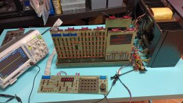
Inspired by Jerry Walker's videos I created a test bench with the first backplane connected to the power supply.
Like Jerry I fitted 4 large spacers to the backplane to protect the wire-wrap pins.
Into the backplane I plugged in two terminators and the M7859 console controller.
I connected the actual console to the controller, 5V & GND and J3 on the power supply.

Of course at first I got the console to controller ribbon cable orientation wrong because I believed the KY11-LB maintenance manual. :(
Fortunately I found the following page on Gunkies.org:

https://gunkies.org/wiki/KY11-LB_Programmer's_Console

There the author nicely points out the mistake and the correct orientation of the ribbon cable.

On the web page above there is a link to other web sites of interest. One of them caught my eye:

PDP-11/34 programmer's console as UNIBUS diagnostic tool

The page says under header "3.SELFTEST":

"The M7859 KY11-LB Programmer Console controls the UNIBUS, and also implements one UNIBUS register: the Switch Register. So you can test an empty UNIBUS by reading the internal Switch Register back over UNIBUS with a EXAM (DATI cycle) to 777570."

Here is a photo of my test bench just after executing the self test described above (as always click on the photo to see full size):

IMG_20230916_212955750.jpg

So there are first signs of life. :)

Initially some of the digits on the 7 segment display had missing segments. After re-seating the affected 7 segment modules they came back to life.
 
A finger is twitching :-}.
Sorry but I am not quite sure what you are saying??? Maybe this is a US versus OZ linguistic trap. :)

I have a spare console & M7859.

The spare console appears to be mostly working except some of the keypad keys are difficult to operate - the Zero key is really bad and takes several presses to register.

Has anyone tried to disassemble and clean the keypad? Are there any hidden dragons there?

The spare M7859 is not working. The 8008 gets a clock which is about 700 kHz as opposed to the 1 MHz on the good M7859. I have no great ideas how to debug and fix this and would appreciate any help or suggestions.
 
Back
Top